Interference resistant infrared extension system

a technology of infrared extension and control system, which is applied in the direction of electromagnetic transmission, electrical apparatus, electromagnetic repeaters, etc., can solve the problems of affecting the use of the system,

Inactive Publication Date: 2007-03-20
CORE BRANDS
View PDF15 Cites 74 Cited by
  • Summary
  • Abstract
  • Description
  • Claims
  • Application Information

AI Technical Summary

Benefits of technology

The present invention provides a method for detecting an optical communication signal, converting it to an electrical signal, amplifying it, and filtering it to prevent interfering signals from being converted to an electrical signal. This results in a higher quality electrical signal that is easier to detect and analyze.

Problems solved by technology

The technical problem addressed in this patent text is the absence of a suitable interference-resistant broadband IR receiver that can be used in conventional IR control systems, as well as in repeater configurations. This has created inconveniences for users, such as the inability to control components outside the line-of-site or beyond the transmission range of the component's IR receiver. The text proposes the development of a wideband IR receiver that is resistant to interference from stray IR radiation, which would improve the usability of IR control systems.

Method used


Image

  • Interference resistant infrared extension system
  • Interference resistant infrared extension system
  • Interference resistant infrared extension system

Examples


Embodiment Construction

[0026]In the following description of the preferred embodiment, reference is made to the accompanying drawings that form a part hereof, and in which is shown by way of illustration a specific embodiment in which the invention may be practiced. It is to be understood that other embodiments may be utilized and structural changes may be made without departing from the scope of the present invention.

System Overview

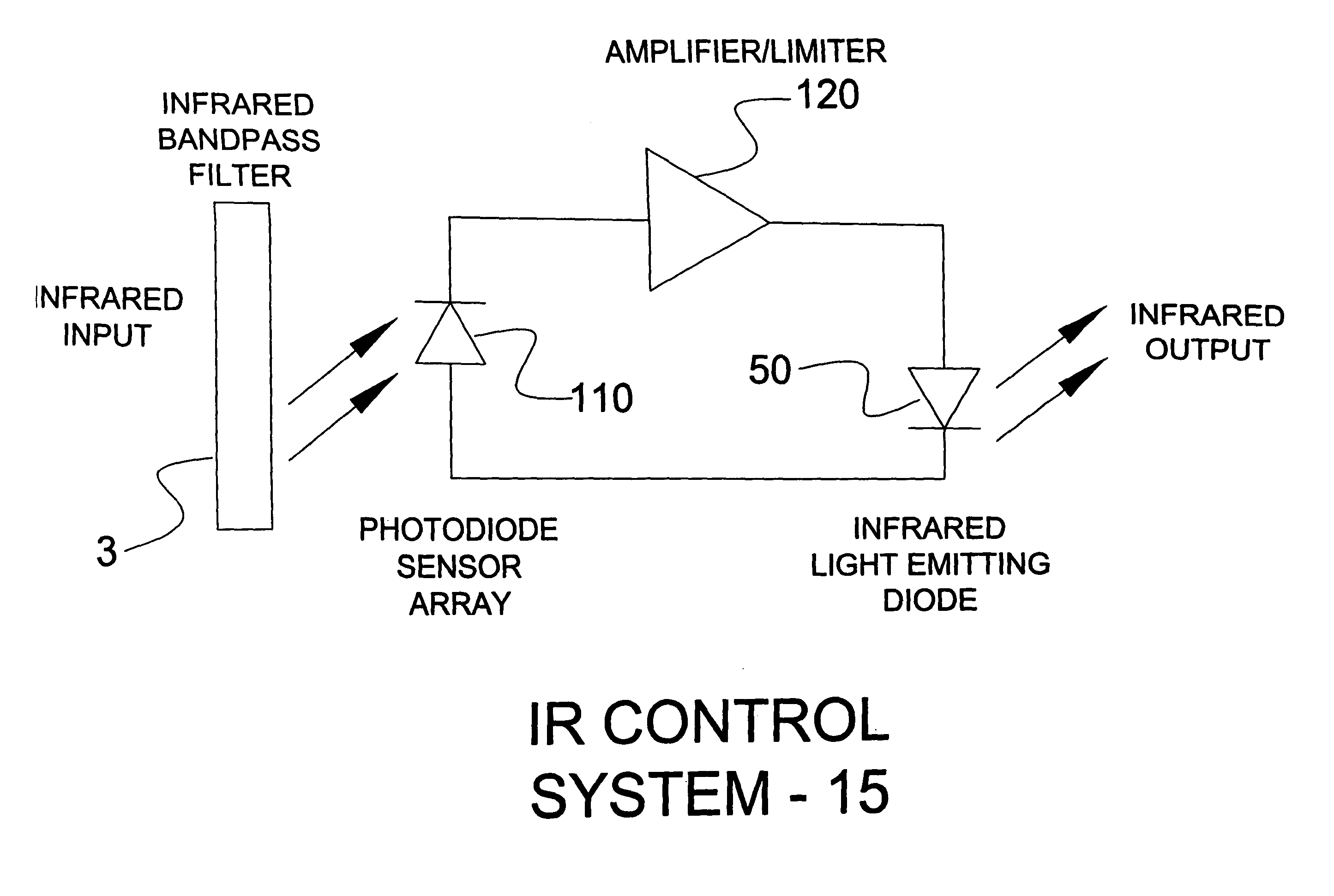
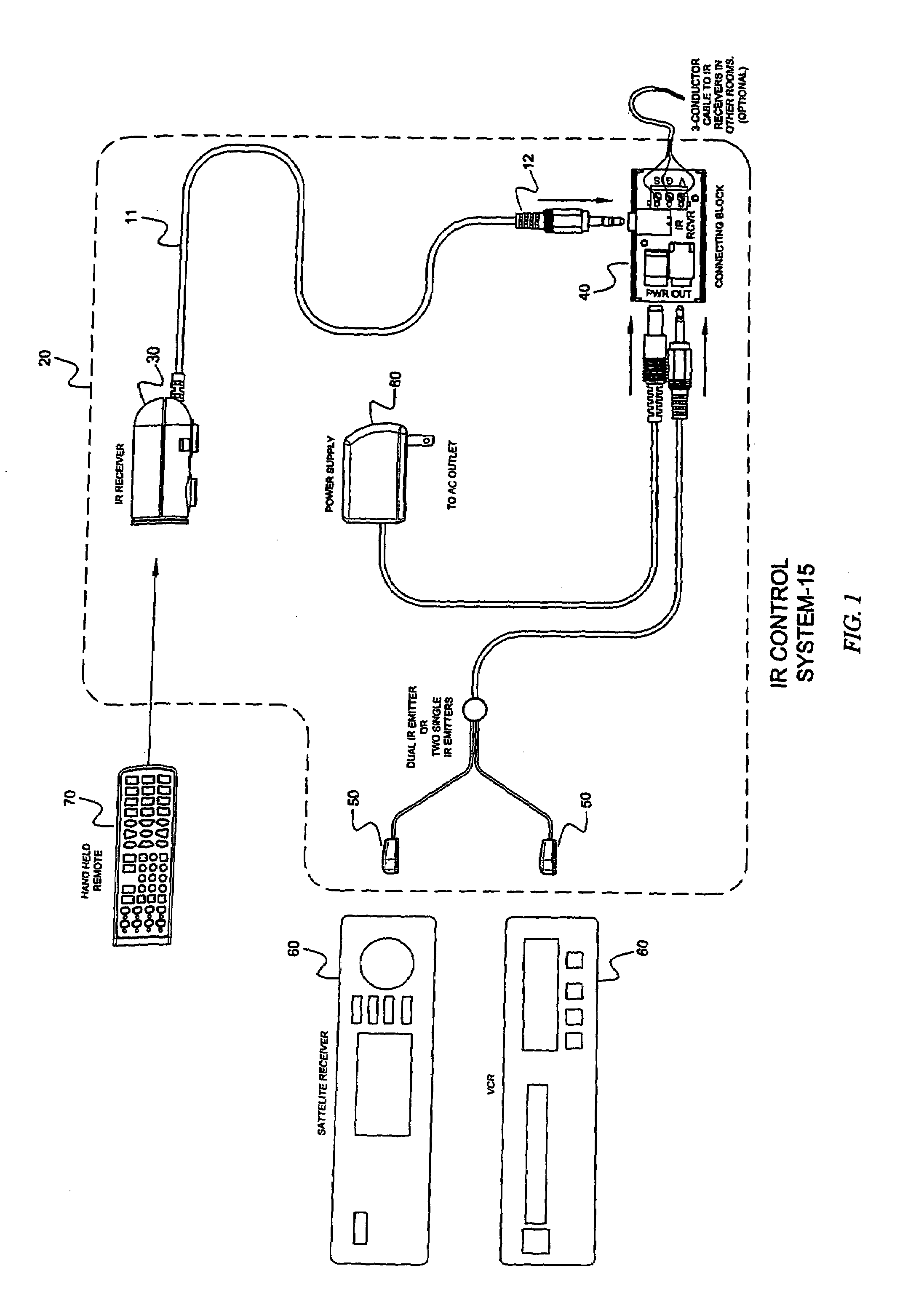
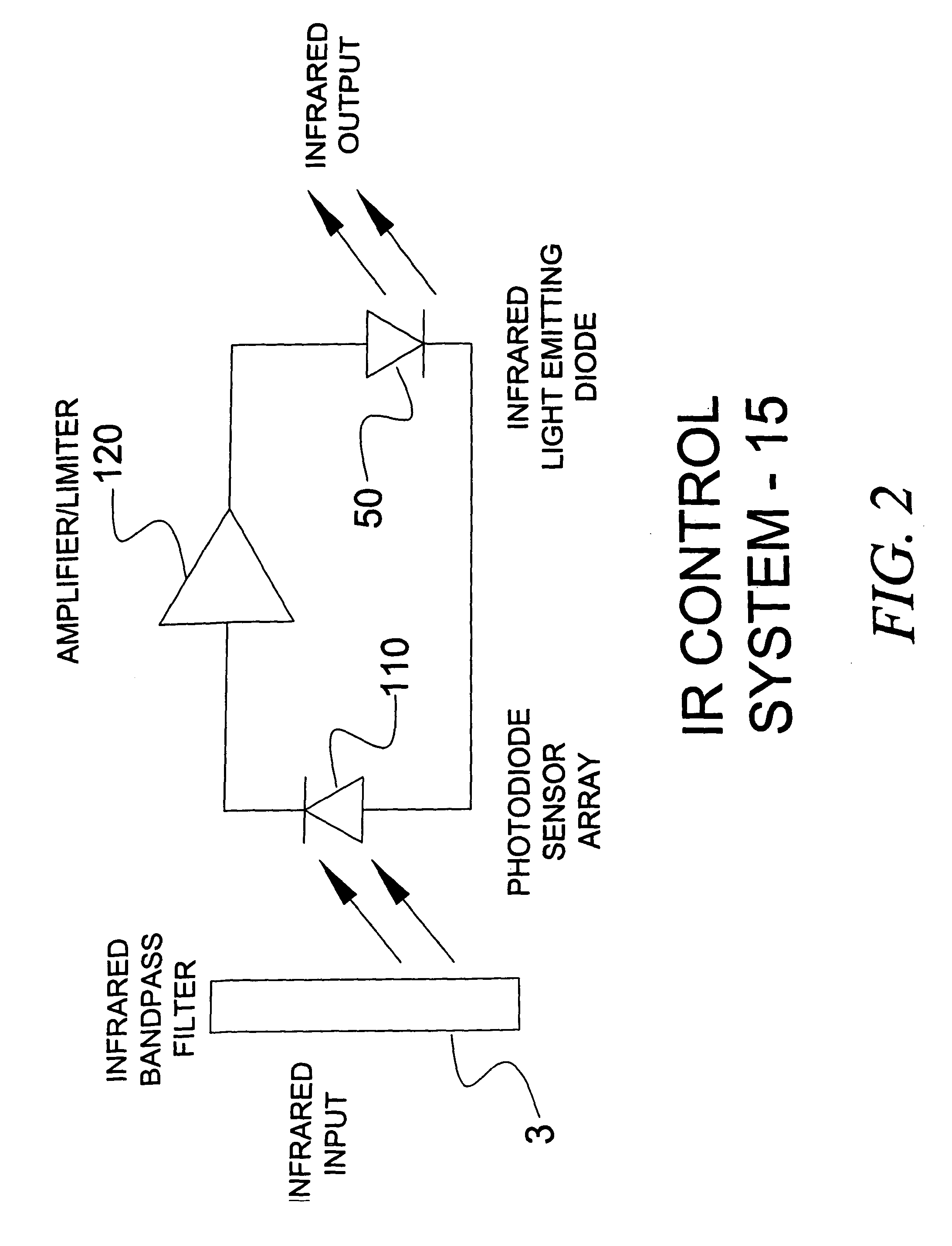
[0027]FIG. 1 illustrates an IR control system 15 comprising one or more IR control transmitters, such as a hand held IR remote 70, an IR extension system 20, and one or more electrical or electromechanical IR controlled appliances or components 60. The IR extension system 20 comprises an IR receiver 30, a connecting block or router component 40, and one or more IR emitters 50 adapted to emit IR light suited to communicate with the IR controlled appliances or components 60. Light emitters 50 may operate at different wavelengths, if desired.

[0028]As illustrated in FIG. 1, the co...


PUM


Abstract

An interference resistant infrared receiver and extension system is disclosed. A receiver in accordance with the present invention comprises at least one infrared photodetector configured to detect impinging infrared light of a desired wavelength, an amplifier, coupled to the at least one infrared photodetector, for amplifying an electrical signal generated by the at least one infrared photodetector, and a bandpass filter, coupled to the at least one infrared photodetector, wherein the desired impinging infrared light passes through the bandpass filter before impinging on the at least one infrared photodetector, wherein the bandpass filter is configured to pass desired impinging infrared light and block undesired impinging wavelengths of light.

Description


Claims


Application Information

Patent Timeline
Owner CORE BRANDS
Why Eureka
Try Eureka