

Optical sensing device containing fiber bragg gratings
a fiber bragg grating and optical sensing technology, which is applied in the direction of instruments, optical elements, heat measurement, etc., can solve the problems of large wavelength shifts which place the gratings outside the filter bandwidth, low sample rate, and difficult low-frequency interrogation of the interferometer, etc., to achieve limit the bandwidth or the effect of dynamic rang
Inactive Publication Date: 2002-04-11
THE UNITED STATES OF AMERICA AS REPRESENTED BY THE SECRETARY OF THE NAVY
View PDF0 Cites 104 Cited by
- Summary
- Abstract
- Description
- Claims
- Application Information
AI Technical Summary
Benefits of technology
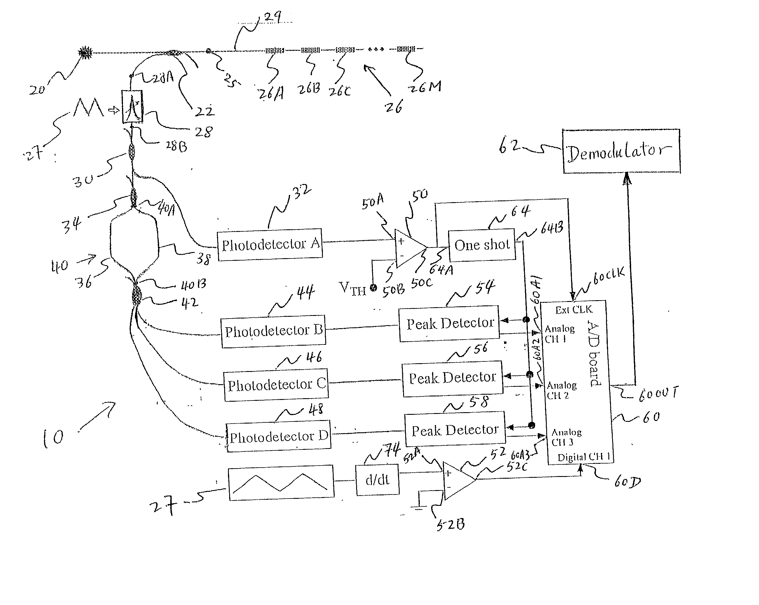
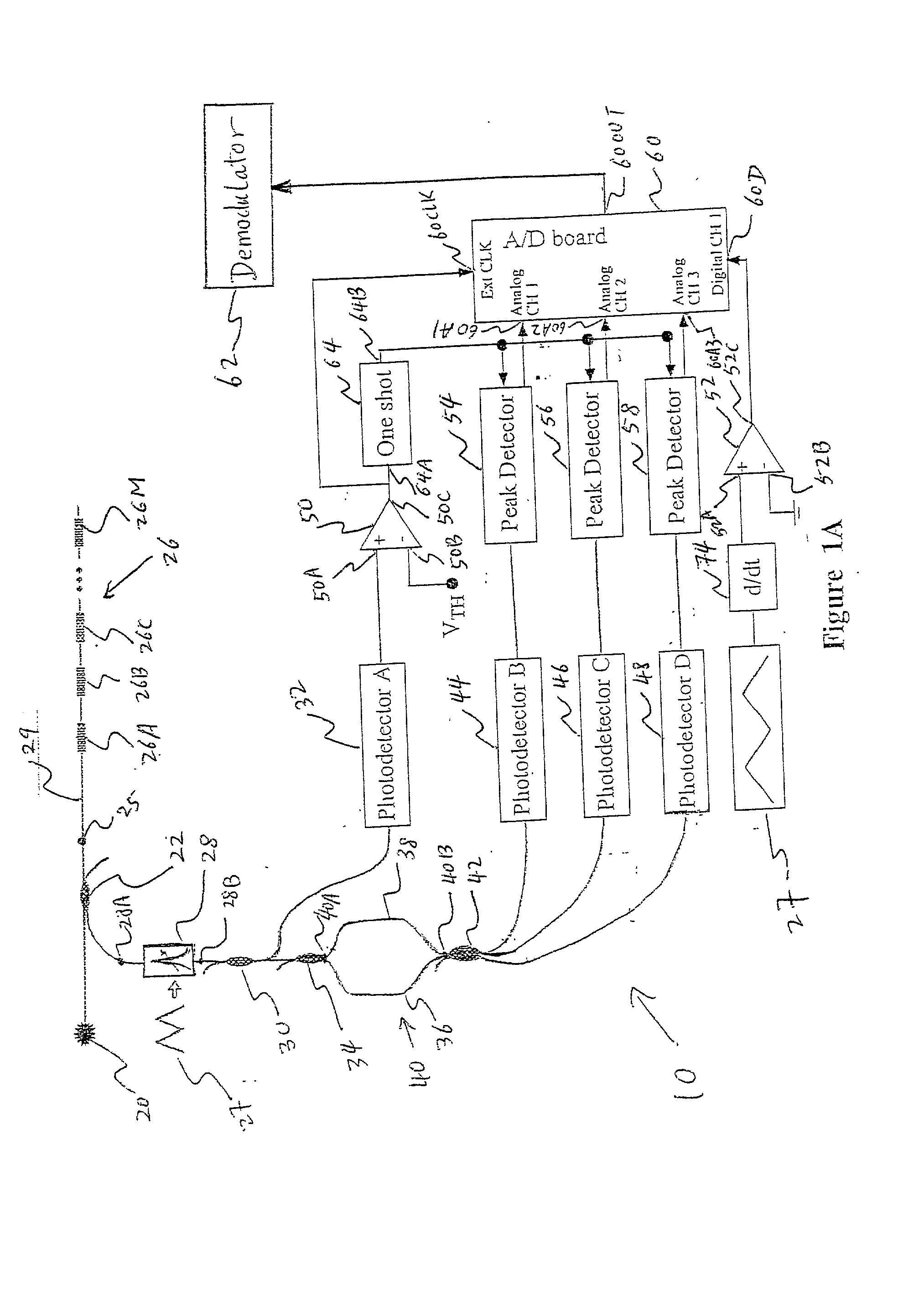
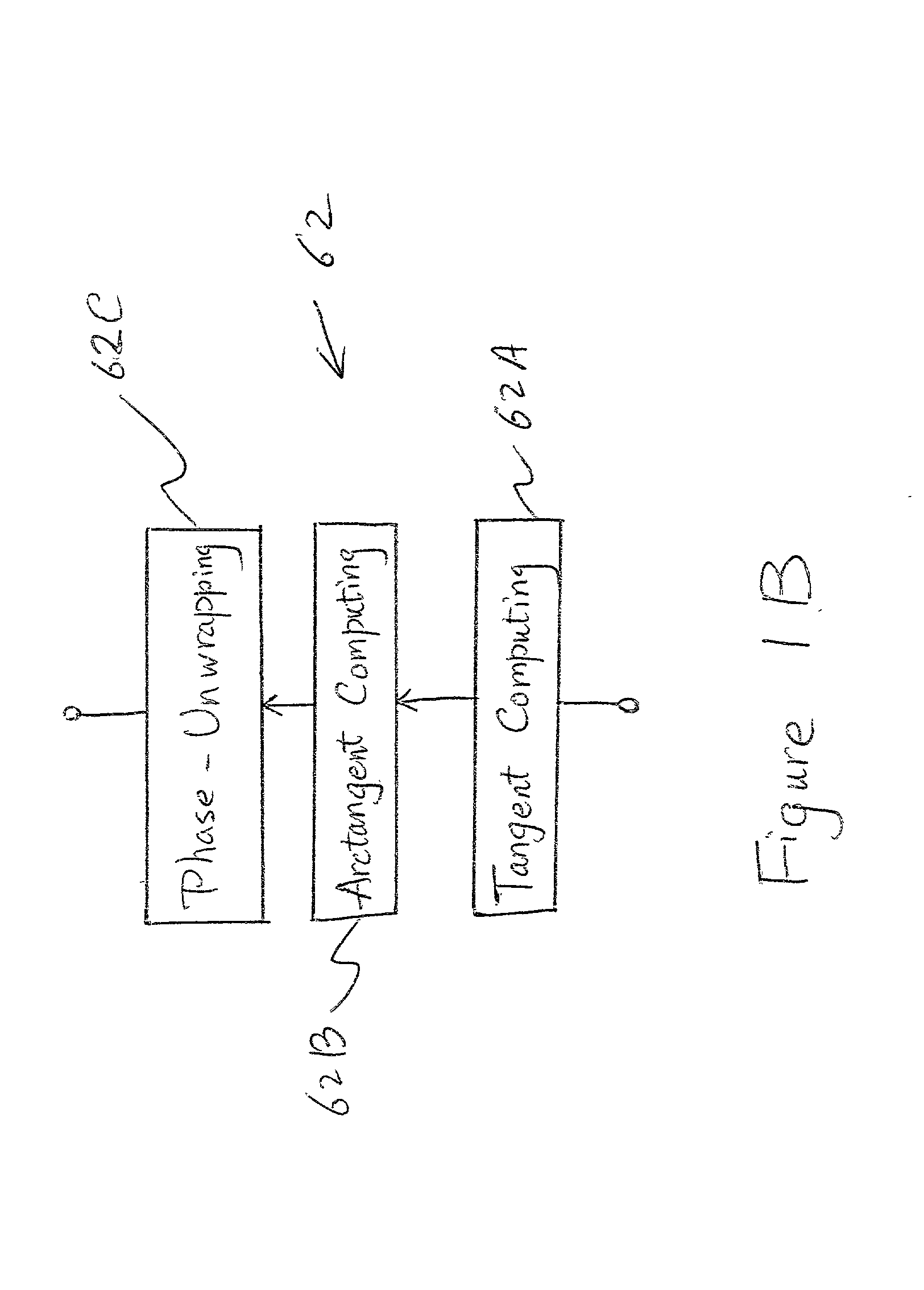
[0063] Equation (4) allows for robust recovery of .phi. by using an arctangent algorithm with appropriate phase unwrapping for signals exceeding 2.pi. in amplitude. The general form of this algorithm is as follows: the values tan .phi. and -cot .phi. are obtained by equation (4) and its negative reciprocal. The arctangent function is then applied to one of these values on the .vertline.tan .phi..vertline.; if .vertline.tan .phi..vertline.<1(.phi.<.pi. / 4), then arctan(tan .phi.) is computed, else -arctan(cot .phi.) is computed. This calculation allows for complete continuous coverage of the unit circle. For unwrapping, a series of Boolean tags is associated with each phase computation, and increments of .+-.2.pi. are added to the current phase computation by both comparing past and present Boolean values and past and present information pertaining to the quadrant of the phase computation. The entire demodulation algorithm including the unwrapping algorithm is incorporated directly into a programmable logic chip 362. The output 362A of the programmable chip 362 is sent to a computer 376 for further data processing and storage. Optionally, the entire demodulation process can be realized in computer 376 containing a program encoding the demodulation algorithm. Therefore, the demodulator may be included in computer 376. Once the phase shift f is recovered, the resulting strain on the grating may be calculated by the relationship: 3 = 2 nd ( 5 )
[0066] This method of obtaining .phi. (demodulation) offers some advantages over previous methods of 3.times.3 demodulation (Koo et al, Appl. Phys. Lett. 40, 616-18, 1982; Lo et al, J. Lightwave Tech., 15, 1578-86, 1997; Lo, Photon. Technol. Lett., 10, 1003-5, 1998). The method of the present invention is completely passive, and as such no active devices are present which may limit bandwidth or dynamic range. The method of the present invention is immune to source or polarization-induced intensity fluctuations in the sense that such fluctuations will not be falsely interpreted as strain.
Problems solved by technology
Accordingly, large wavelength shifts which place the gratings outside the filter bandwidths cannot be tolerated.
For this reason, and because very low-frequency interrogation of the interferometer is difficult due to inherent drift destabilization, the WDM system is often used for high-frequency, low-amplitude measurements.
From a system performance perspective, the SFP filter systems tend to have a low sample rate (<1 kHz) due to limitations in the required electronics and a dynamic noise floor of roughly 100 n.epsilon.Hz.sup.-1 / 2, while the interferometer-based systems may have a measurement bandwidth up to tens of kilohertz and a noise floor of 5-10 n.epsilon.Hz.sup.-1 / 2 at 100 Hz, with a rapidly rising noise floor approaching the static end of the frequency spectrum due to active component requirements.
The largest error in the compensated signal occurred during the most rapid rise of the temperature in the first hour of the test, and the most likely source of error here is the mismatch in thermal inertias of the glass and aluminum substrates to which the reference gratings 324A and 324B were bonded.
Method used
View moreImage
Smart ImageViewing Examples

Examples
Embodiment Construction
and examples are not intended to limit the scope of the invention in any way and should not be construed as limiting the scope of the invention. The scope of the invention is to be determined from the claims appended hereto.
Login to View More PUM
| Property | Measurement | Unit |
|---|---|---|
| optical length | aaaaa | aaaaa |
| frequency | aaaaa | aaaaa |
| wavelength shift | aaaaa | aaaaa |
Abstract
A new optical sensing device containing fiber Bragg gratings, a scanning bandpass filter, an interferometer and multiple photodetectors is disclosed. The present invention also describes a new system and method for fibre Bragg grating (FBG) sensor interrogation and multiplexing. The new system combines a scanning Fabry-Perot (SFP) bandpass filter used to wavelength-multiplex multiple gratings in a single fiber, and an unbalanced Mach-Zehnder fibre interferometer made with a 3x3 coupler to detect strain-induced wavelength shifts. A passive technique for interferometer drift compensation using non-sensing FBGs is included in the system. A complete prototype system interrogates four gratings in a single fiber at a Nyquist sampling rate up to 10 kHz, with a noise floor measured near 4 nepsi Hz-½ above 0.1 Hz. The inclusion of the interferometer drift compensation technique is shown to make quasi-static measurements feasible.
Description
[0001] 1. Field of the Invention[0002] The present invention relates to an optical sensing device which employs fiber Bragg grating and includes both a scanning filter and an interferometer which together function as the interrogation and multiplexing system of the sensing device.[0003] 2. Description of the Prior Art[0004] The introduction of fiber Bragg gratings (FBG's) and the development of subsequent techniques with which to mass-produce them has spurred significant research activity in the development of FBG-based sensors and interrogation systems that detect shifts in the center wavelengths of the gratings. The wavelength shifts are caused by axial strains exerted on the fiber in which the gratings are written. This has led to widespread application of gratings in strain gauges (Kersey et al, J. Lightwave Tech., 15, 1442-63,1997; Vohra et al, IEICE Trans. Electron., E83-C, 454-61,2000; Maaskant et al, Cement Concrete Composites, 19, 21-3, 1996; Todd et al, Proc. Int. Modal An...
Claims
Login to View More Application Information
Patent Timeline
 Patent Type & AuthorityApplications(United States)
IPC IPC(8): G01D5/353G01K11/32
CPCG01D5/35383G01L1/246G01L1/243G01K11/3206
InventorJOHNSON, GREGG A.TODD, MICHAEL D.CHANG, CHIA-CHENALTHOUSE, BRYAN L.
OwnerTHE UNITED STATES OF AMERICA AS REPRESENTED BY THE SECRETARY OF THE NAVY