Signal conditioning circuit between an optical device and a processing unit

a technology of optical devices and processing units, applied in the direction of transmission, sensors, catheters, etc., can solve the problems of limited usable gain range of amplifiers, limited space occupied in portable instruments, and limited power consumption, and achieve the limitation of available space and power consumption

Active Publication Date: 2007-09-13
EM MICROELECTRONIC-MARIN
View PDF7 Cites 108 Cited by
  • Summary
  • Abstract
  • Description
  • Claims
  • Application Information

AI Technical Summary

Benefits of technology

[0008]The present invention therefore concerns a conditioning circuit for an external signal representative of a physiological quantity between an optical sensor and a processing unit, the received external signal being broken down into a useful component and an ambient component, characterized in that the conditioning circuit comprises a first stage including a transimpedance amplifier with an incorporated high pass filter using a feedback loop for subtracting, at the stage input, the ambient signal component from the received external signal and for delivering, at output, an amplified useful signal, a second stage comprising a locker sampling circuit for demodulating the amplified useful signal and delivering at output a demodulated useful signal, and a third stage comprising a bandpass filter for filtering the demodulated useful signal in the frequency band of the physiological quantity to be detected and for transmitting a conditioned signal to the processing unit.

Problems solved by technology

Nonetheless, within the scope of the present invention, it has been demonstrated that this solution is not optimal insofar as the ambient signal that is a component of the received external signal IN is also amplified through amplifier 81, which considerably limits the usable gain range of the amplifier to prevent the latter becoming saturated.
Moreover, this portable instrument and more particularly the conditioning circuit for conditioning the signals received by the optical sensor prior to processing by the central processing unit, has certain drawbacks, particularly in terms of the space occupied in the portable instrument and in terms of power consumption.
Indeed, in this portable electronic instrument, two major concerns are typically the available space and power consumption which are both limited.
A conditioning circuit like that presented in the prior art has a non-optimum occupied surface area in that it uses a certain number of discrete components to perform the functions of amplification, filtering and detection.
Moreover, each of these functions has non-optimised energy consumption because of the use of numerous operational amplifiers.

Method used


Image

  • Signal conditioning circuit between an optical device and a processing unit
  • Signal conditioning circuit between an optical device and a processing unit
  • Signal conditioning circuit between an optical device and a processing unit

Examples


Embodiment Construction

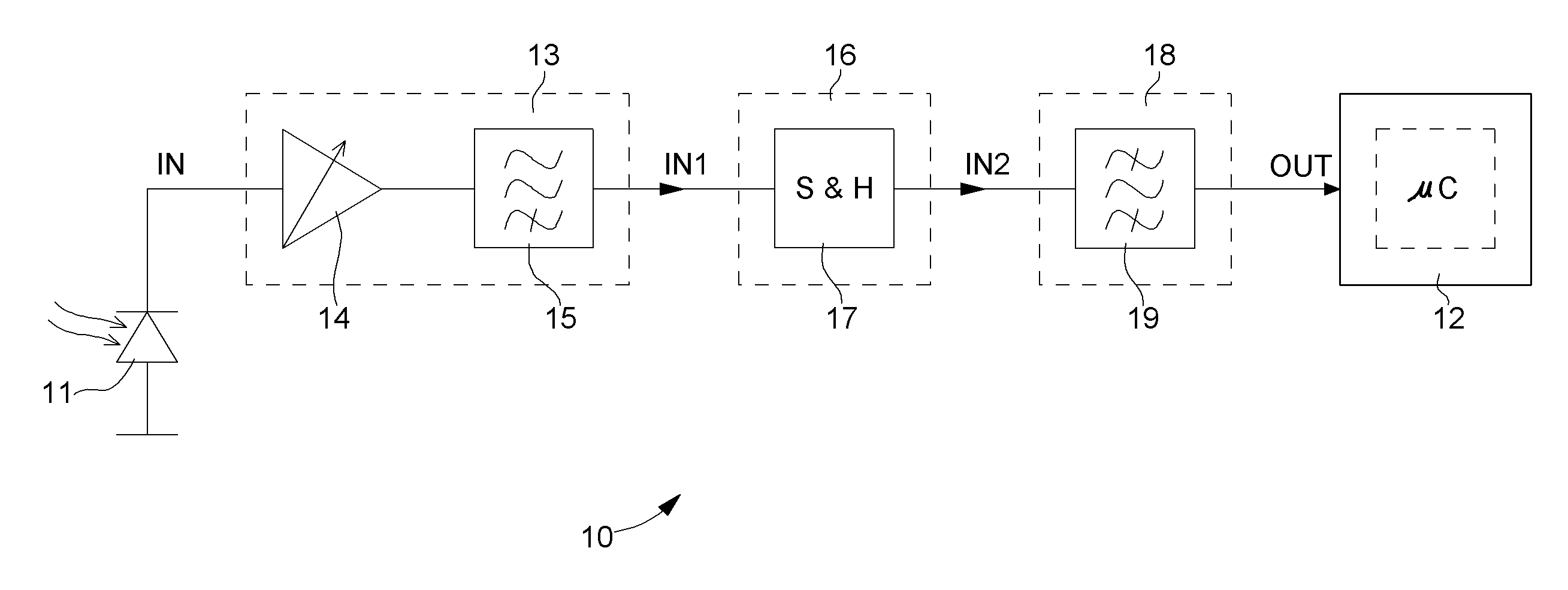
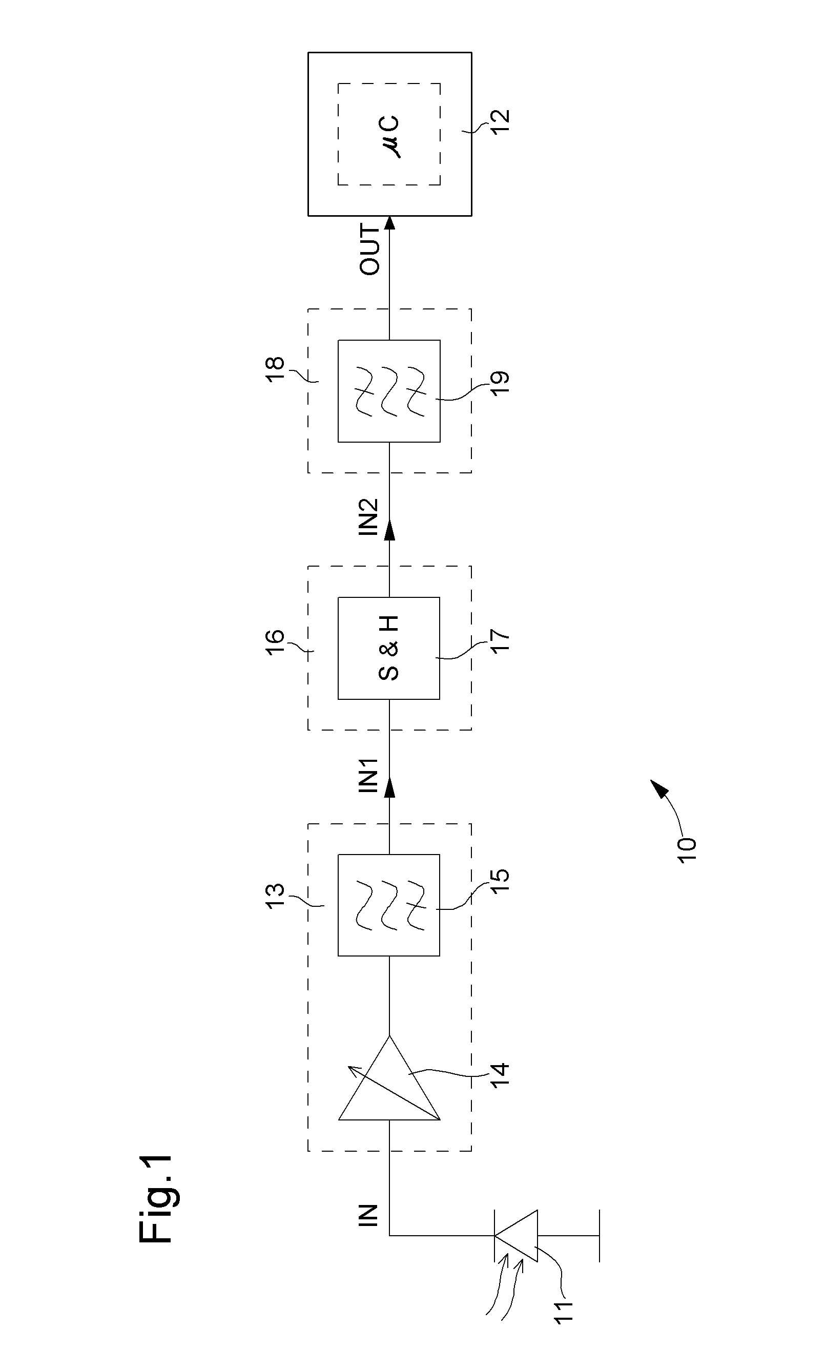
[0027]The various embodiments that will now be presented are given solely by way of non-limiting illustration. FIG. 1 is a flow chart showing the whole of conditioning circuit 10 according to one embodiment of the invention. For the sake of general comprehension, FIG. 1 also shows an optical sensor 11, like for example a photodiode, a phototransistor or any other suitable optical receiver receiving an external signal IN for measuring a physiological quantity, particularly the heart rate. This external signal IN is a current signal comprising an ambient component and a useful component, said signal being obtained for example by means of an optical device including at least one light source (not shown) for subjecting a portion of an organic tissue to a light emission and at least one photoreceptor, i.e. optical sensor 11, for detecting the intensity of the light emission after propagation in the organic tissue. A central processing unit 12 is also shown, such as a microprocessor or mi...


PUM


Abstract

The invention concerns a conditioning circuit (10) for an external signal (IN) representative of a physiological quantity, arranged between an optical sensor (11) and a processing unit (12), the received external signal (IN) being broken down into a useful component and an ambient component, characterized in that the conditioning circuit includes a first stage (13) including a transimpedance amplifier with an incorporated high pass filter (15) using a feedback loop to subtract the ambient signal component from the received external signal, and to deliver at output an amplified useful signal (IN1), a second stage (16) including a blocker sampler circuit (17) for demodulating the amplified useful signal and delivering at output a demodulated useful signal (IN2), and a third stage (18) including a bandpass filter (19) for filtering the demodulated useful signal in the frequency band of the physiological quantity to be detected and for transmitting a conditioned signal (OUT) to the processing unit.

Description

FIELD OF THE INVENTION[0001]The present invention concerns, generally, a conditioning circuit for the signal between an optical sensor for measuring a physiological quantity, particularly the heart rate, and a digital processing unit for received signals. The invention concerns more specifically the various stages of the conditioning unit, in particular, the amplification, locking sampling and filtering stages. The invention also concerns an integrated circuit comprising this conditioning circuit. The invention further concerns a portable electronic instrument including such an integrated circuit.BACKGROUND OF THE INVENTION[0002]There is known from the prior art, in particular from EP Patent No. 1 484 009, a portable instrument provided with an optical device for measuring a physiological quantity. This document describes in particular, as shown in FIG. 6, a portable instrument including a light source 61 (for example a light emitting diode, i.e. LED, or any other suitable device) c...

Claims


Application Information

Patent Timeline
Patent Type & Authority Applications(United States)
IPC IPC(8): H04B17/02H04B17/40
CPCA61B5/0245
Inventor NOVAC, PINCHAS
Owner EM MICROELECTRONIC-MARIN
Why Eureka
Try Eureka