Energy transfer type power battery quick balancing system and control method

A power battery pack and energy transfer technology, applied in battery circuit devices, secondary battery repair/maintenance, current collectors, etc. , expand the scope of application, improve the effect of the equalization rate

Inactive Publication Date: 2011-08-31
HARBIN INST OF TECH
View PDF3 Cites 46 Cited by
  • Summary
  • Abstract
  • Description
  • Claims
  • Application Information

AI Technical Summary

Problems solved by technology

[0003] The purpose of the present invention is to provide an energy-transfer type fast equalization system and control method for power battery packs, so as to solve the problem that both the current waveform at the input end and the current waveform at the output end of the buck-boost converter in the prior art equalizer are sawtooth waves, so that the equalized The problem of battery cells and energy storage components being impacted by pulsating currents

Method used


Image

  • Energy transfer type power battery quick balancing system and control method
  • Energy transfer type power battery quick balancing system and control method
  • Energy transfer type power battery quick balancing system and control method

Examples


specific Embodiment approach 1

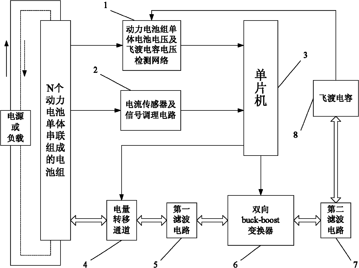
[0016] Specific implementation mode one: the following combination figure 1 This embodiment will be specifically described. This embodiment includes a single cell voltage of a power battery pack and a flying capacitor voltage detection network 1, a current sensor and a signal conditioning circuit 2, a single chip microcomputer 3, a power transfer channel 4, a first filter circuit 5, a bidirectional buck-boost converter 6, The second filter circuit 7 and the flying capacitor 8;

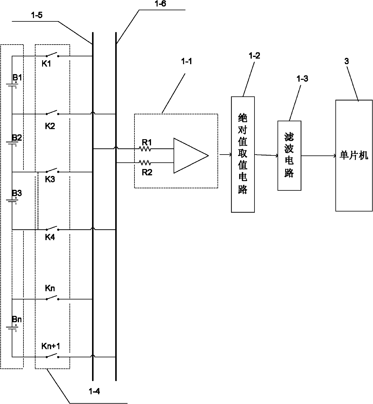
[0017] Power battery pack cell voltage and flying capacitor voltage detection network 1: connect the balanced power battery pack and flying capacitor 8 to detect the voltage value of each single cell in the battery pack and the voltage value of the flying capacitor, and collect the The voltage value of each is passed to the single-chip microcomputer 3;

[0018] Current sensor and signal conditioning circuit 2: connected to the battery pack to detect the charging and discharging current of the power ...

specific Embodiment approach 2

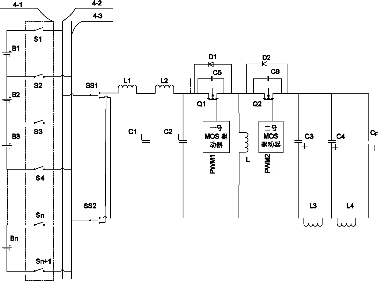
[0025] Specific implementation mode two: the following combination image 3 This embodiment will be specifically described. The difference between this embodiment and Embodiment 1 is that: the first filter circuit 5 , the bidirectional buck-boost converter 6 and the second filter circuit 7 together constitute an improved bidirectional buck-boost converter. The converter consists of the first switch tube Q1, the second switch tube Q2, the diode D1, the second tube D2, the inductor L, the first switch tube Q1 buffer capacitor C5, the second switch tube Q2 buffer capacitor C6, and the first MOS driver and No. 2 MOS driver. The first filter circuit 5 is composed of inductor L1, inductor L2, capacitor C1 and capacitor C2. The second filter circuit 7 is composed of inductor L3, inductor L4, capacitor C3 and capacitor C4. One end of inductor L1 Connect a static terminal of the first switch SS1 to a static terminal of the second switch SS2, the other end of the inductor L1 is connect...

specific Embodiment approach 3

[0026] Specific implementation mode three: the following combination image 3 This embodiment will be specifically described. The difference between this embodiment and Embodiment 1 is that the power transfer channel 4 is composed of a relay array 4-1, odd-numbered nodes connected to the balanced bus 4-2, even-numbered nodes connected to the balanced bus 4-3, the first switch SS1 and the second No. switch SS2, one end of each relay located in an odd position in the relay array 4-1 is connected to an odd node and connected to the balanced bus 4-2, and each of the relays located in an even position in the relay array 4-1 One end of each relay is connected to the even-numbered nodes and connected to the balanced bus 4-3 of the even-numbered nodes, the moving end of the first switch SS1 is connected to the odd-numbered nodes and connected to the balanced bus 4-2, and the second switch SS2 is connected to the even-numbered nodes Connect the equalization bus 4-3.

[0027] image ...


PUM


Abstract

The invention relates to an energy transfer type power battery quick balancing system and a control method thereof. The invention relates to the battery voltage balancing system and further relates to the control method of battery pack quick balancing process, which solves the problem that a balanced battery single body and an energy storing element are impacted through pulse current by a currentbalancer in the prior art. The system comprises a power battery pack single body battery voltage and flying capacitor voltage detecting network, a current sensor and a signal modulating circuit, a single chip microcomputer, an electric power transfer channel, a first filter circuit, a two-way buck-boost converter, a second filter circuit and a flying capacitor. After starting to work, the system firstly detects the battery pack single body battery voltage, the flying capacitor voltage and the charging/discharging current; and if the dropout voltage between the highest voltage of the battery single body and the lowest voltage of the single body exceeds a set value, the balancing operation is started.

Description

technical field [0001] The invention relates to a battery pack voltage equalization system, and the invention also relates to a control method for a fast equalization process of the battery pack. Background technique [0002] The traditional battery pack voltage balancing system is generally energy-consuming. When balancing the voltage of each single battery in the battery pack, the power of the battery with high voltage must be consumed, resulting in unnecessary consumption of energy and heat generation at the same time, resulting in the balance of the system. Work is unreliable. Patent No. ZL200810137146.5 discloses a fast charging and discharging equalization device for battery packs or supercapacitor packs. Figure 14 The main circuit diagram of the equalizer is given. This patent proposes a non-energy-consuming battery pack voltage equalization method, but if Figure 12a )and Figure 11a ) shows, the basic bidirectional buck-boost converter circuit structure input cu...

Claims


Application Information

Patent Timeline
Patent Type & Authority Applications(China)
IPC IPC(8): H01M10/42H02J7/00
CPCY02E60/12Y02E60/10
Inventor 朱春波逯仁贵夏小东
Owner HARBIN INST OF TECH
Why Eureka
Try Eureka