
Apparatus and method for rangings and noise reduction of low coherence interferometry lci and optical coherence tomography oct signals by parallel detection of spectral bands

a technology of optical coherence interferometry and oct signals, which is applied in the field of apparatus and method for ranging and noise reduction of low coherence interferometry lci and optical coherence tomography oct signals by parallel detection of spectral bands, can solve the problem of the power that is allowed for ophthalmic applications, and achieve the effect of increasing the snr of lci

Inactive Publication Date: 2008-04-24
THE GENERAL HOSPITAL CORP
View PDF99 Cites 106 Cited by
  • Summary
  • Abstract
  • Description
  • Claims
  • Application Information

AI Technical Summary

Benefits of technology

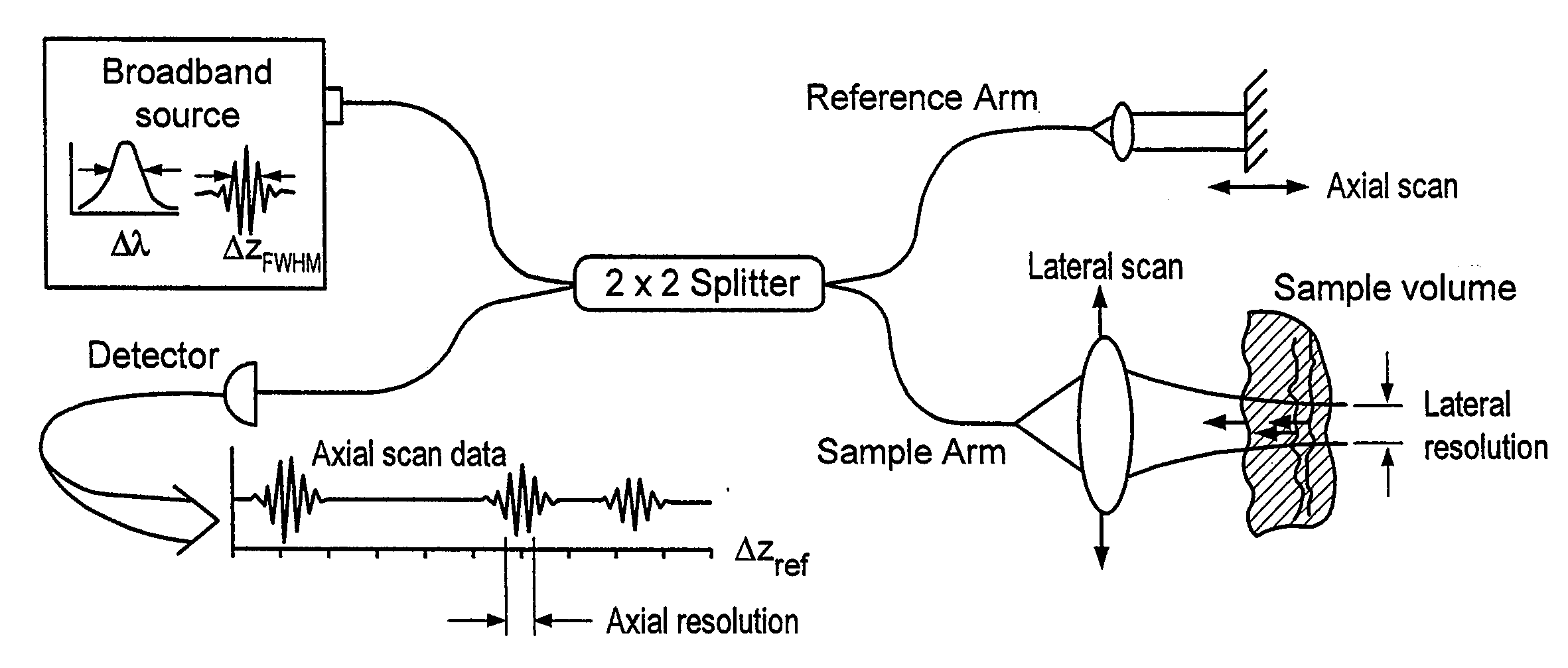
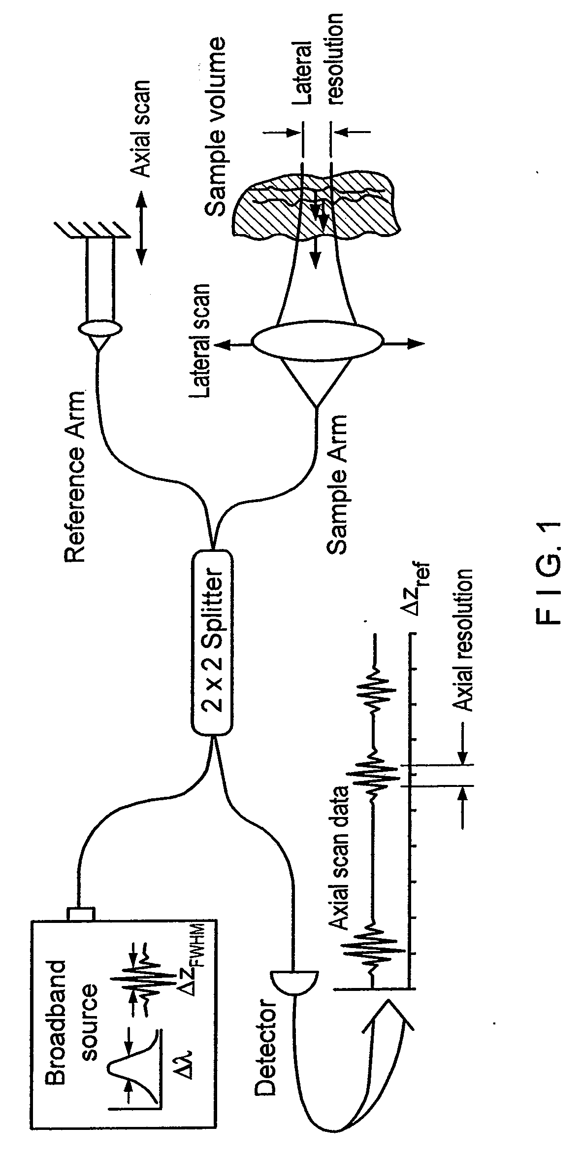
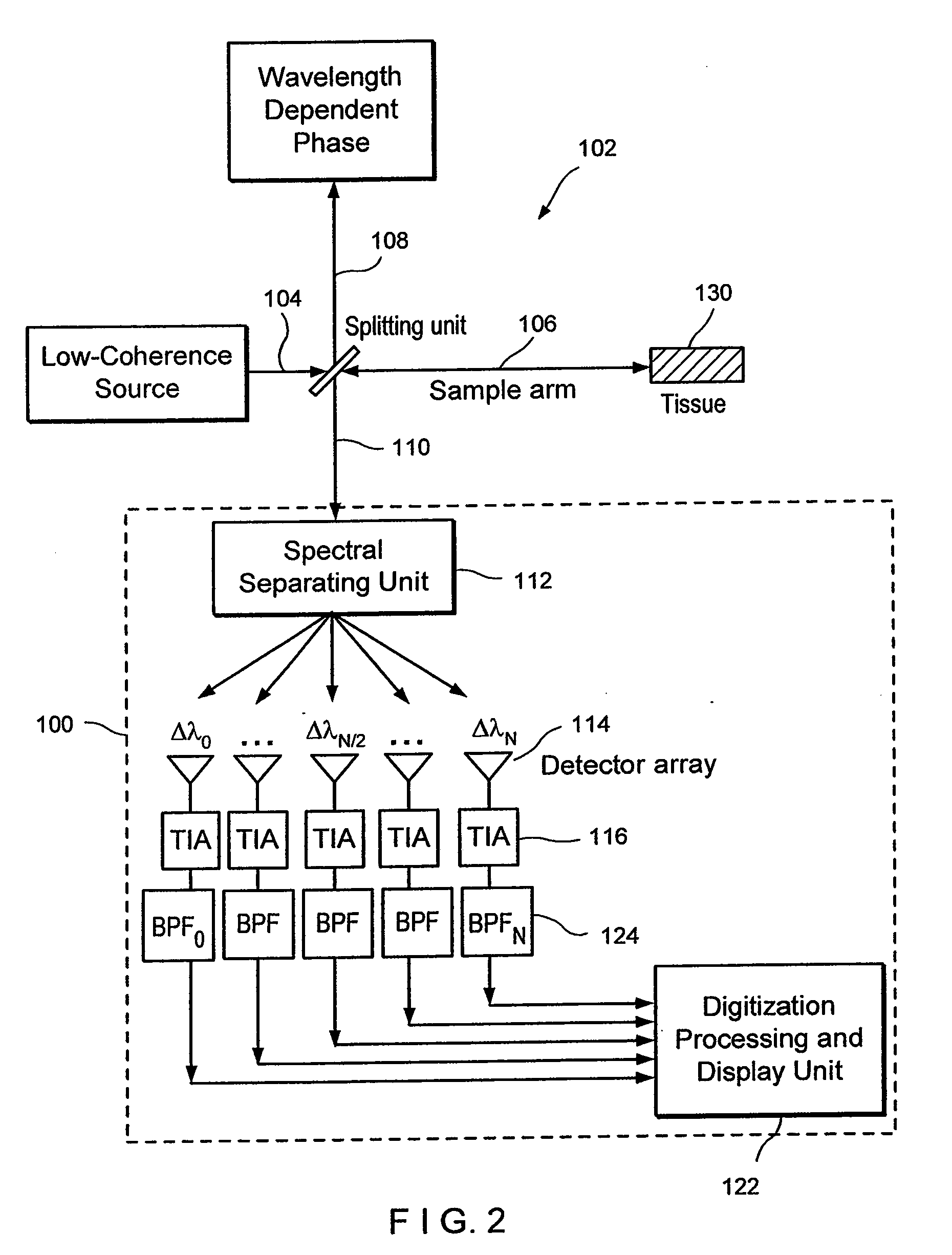
[0005] The present invention increases the SNR of LCI and OCT by splitting the LCI broad bandwidth source into N spectral bands. The N spectral bands are individually detected and processed to provide an increase in the SNR by a factor of N. This increase in SNR enables LCI or OCT imaging by a factor of N times faster, or alternatively allows imaging at the same speed with a source that has N times lower power. As a result, the present invention overcomes two of the most important shortcomings of LCI and OCT, i.e., source availability and scan speed. The factor N may reach more than 1,000, and allows construction of OCT and LCI systems that can be more than three orders of magnitude improved from OCT and LCI technology currently in practice.
[0006] The present invention enables a breakthrough in current data acquisition speeds and availability of sources for OCT. The shot noise reduction allows for much lower source powers, or much higher acquisition rates than current systems. Limitations in current data acquisition rates (approximately 4 frames / sec) are imposed by available source power. An increase in the sensitivity of the detection by a factor of 8 would allow real time imaging at a speed of 30 frames per second. An increase of the sensitivity by a factor of 1,000-2,000 would allow for the use of sources with much lower powers and higher spectral bandwidths which are readily available, cheaper to produce, and can generate broader bandwidths.
[0007] For ophthalmic applications of OCT, the efficient detection would allow for a significant increase of acquisition speed. The limitation in ophthalmic applications is the power that is allowed to enter the eye according to the ANSI standards (approximately 700 microwatts at 830 nm). Current data acquisition speed in ophthalmic applications is approximately 100-500 A-lines per second. The power efficient detection would allow for A-line acquisition rates on the order of 100,000 A-lines per second, or video rate imaging at 3,000 A-lines per image.

Problems solved by technology

The limitation in ophthalmic applications is the power that is allowed to enter the eye according to the ANSI standards (approximately 700 microwatts at 830 nm).

Method used


Image

  • Apparatus and method for rangings and noise reduction of low coherence interferometry lci and optical coherence tomography oct signals by parallel detection of spectral bands
  • Apparatus and method for rangings and noise reduction of low coherence interferometry lci and optical coherence tomography oct signals by parallel detection of spectral bands
  • Apparatus and method for rangings and noise reduction of low coherence interferometry lci and optical coherence tomography oct signals by parallel detection of spectral bands

Examples


case b

ike Spectral Bands and the Reconstruction of the Full Depth Range in the Sample Arm from Reduced Reference Arm Scans.

[0065] The following discussion describes the principle of reconstruction of the full depth range in the sample arm from reduced reference arm scans. The procedure will be explained in the case of demultiplexing the spectrum in two spectral bands. The method can be expanded for demultiplexing into many spectral bands.

[0066] The signal at the detector for a single detector system is given by R(t). The depth range in the sample is given by the measurement time T of a single A-line (depth profile) times the group velocity generated by the reference arm delay line,

zrange=vgT

[0067] The smallest resolvable frequency after an FFT is given by 1 / T, which gives a smallest resolvable angular frequency Δω=2π / T. The filter as depicted in FIG. 4 splits the signal into two bands with peaks at ω=ω0, ω0+2Δω, ω0+4Δω, etc. and ω=ω0+Δω, ω0+3Δω, etc., respectively.

[0068] B1(t) and B2(...

case b2

f Large Number of Spectral Bands

[0073] In the limit of a large number of spectral bands, N≥Lλ,

the optical path length change in the reference arm approaches that of a wavelength, λ. In this limit, only a phase change across one wavelength is needed for reconstructing the entire axial scan over length L. In this case, the reference arm path delay may be accomplished by using any of the aforementioned means for scanning the reference arm delay. Other preferred methods include insertion of an electrooptic modulator, acoustooptic modulator or phase control rapidly scanning optical delay line (“RSOD”) in the reference arm path to impart the path length delay of one wavelength. Also in this case, the wavelength demultiplexing unit does not separate the wavelengths into a comb pattern, but demultiplexes the spectrum into unique optical frequencies, with each frequency detected by a single detector.

Case C. Fourier Domain Reconstruction for Arbitrary Wavelength Patterns

[0074] As opposed...

example

[0078] The method was verified in the lab by the following experiment. In the existing OCT system, the shot noise power spectrum as determined from the spectral density due to the reference arm optical power was measured. Then ⅔ of the spectrum from the reference arm was blocked, and experimentally it was verified that the shot noise power spectrum was reduced by a factor of three, thus demonstrating that the shot noise is reduced by a factor of 3 if the spectrum is split in three spectral bands (see FIG. 5). The upper curve (gray dotted line) shows the power spectrum for the OCT signal with one detector. For the lower curve (solid line), the spectrum was limited by ⅓ with a corresponding factor of 3 improvement in signal to noise ratio. This data was generated by experiment, blocking ⅔ of the spectrum in a grating-based double-passed pulse shaping rapidly scanning optical delay line.

[0079] An object with low reflectivity was inserted in the sample arm. Using the full spectral widt...


PUM


Abstract

Apparatus and method for increasing the sensitivity in the detection of optical coherence tomography and low coherence interferometry (“LCI”) signals by detecting a parallel set of spectral bands, each band being a unique combination of optical frequencies. The LCI broad bandwidth source is split into N spectral bands. The N spectral bands are individually detected and processed to provide an increase in the signal-to-noise ratio by a factor of N. Each spectral band is detected by a separate photo detector and amplified. For each spectral band the signal is band pass filtered around the signal band by analog electronics and digitized, or, alternatively, the signal may be digitized and band pass filtered in software. As a consequence, the shot noise contribution to the signal is reduced by a factor equal to the number of spectral bands. The signal remains the same. The reduction of the shot noise increases the dynamic range and sensitivity of the system.

Description

CROSS REFERENCE TO RELATED APPLICATION [0001] This application claims benefit of copending U.S. provisional patent application No. 60 / 351,904, filed Jan. 24, 2002, entitled APPARATUS AND METHOD FOR RANGING AND SHOT NOISE REDUCTION OF LOW COHERENCE INTERFEROMETRY (LCI) AND OPTICAL COHERENCE TOMOGRAPHY (OCT) SIGNALS BY PARALLEL DETECTION OF SPECTRAL BANDS, and commonly assigned to the assignee of the present application, the disclosure of which is incorporated by reference in its entirety herein.FIELD OF THE INVENTION [0002] The present invention relates to apparatus and a method for dramatically increasing the sensitivity in the detection of optical coherence tomography and low coherence interferometry signals by detecting a parallel set of spectral bands, each band being a unique combination of optical frequencies. BACKGROUND OF THE ART [0003] Two methods currently exist to implement depth ranging in turbid media. The first method is known as Low Coherence Interferometry (“LCI”). Th...

Claims


Application Information

Patent Timeline
Patent Type & Authority Applications(United States)
IPC IPC(8): G01R25/04G01B9/02G01N21/47
CPCA61B5/0059A61B5/0066A61B5/7257G01N21/4795G01B9/0201G01B9/02079G01B2290/45G01B9/02007G01B9/02044G01B9/02008G01B9/0209G01B9/02091G01B9/02032G01B9/02045
Inventor DE BOER, JOHANNES F.TEARNEY, GUILLERMO J.BOUMA, BRETT E.
Owner THE GENERAL HOSPITAL CORP
Learn More