Cord-driven rotator for driving roller of window blind

a technology of driving roller and rotor, which is applied in the direction of door/window protective devices, curtain suspension devices, manufacturing tools, etc., can solve the problem of not being able to hold the lifting cord in pla

Inactive Publication Date: 2007-03-27
NIEN MADE ENTERPRISE CO LTD
View PDF12 Cites 61 Cited by
  • Summary
  • Abstract
  • Description
  • Claims
  • Application Information

AI Technical Summary

Benefits of technology

[0007]It is one objective of the present invention to provide a cord-driven rotator, which has a cord member clamping function that prevents the cord member from slipping relative to the rotator.

Problems solved by technology

Further, after a long time of use of the cord-driven rotator, the V-shaped groove or the recessed round holes may become wear, thereby not enabling to hold the lift cord in place.

Method used


Image

  • Cord-driven rotator for driving roller of window blind
  • Cord-driven rotator for driving roller of window blind
  • Cord-driven rotator for driving roller of window blind

Examples


Embodiment Construction

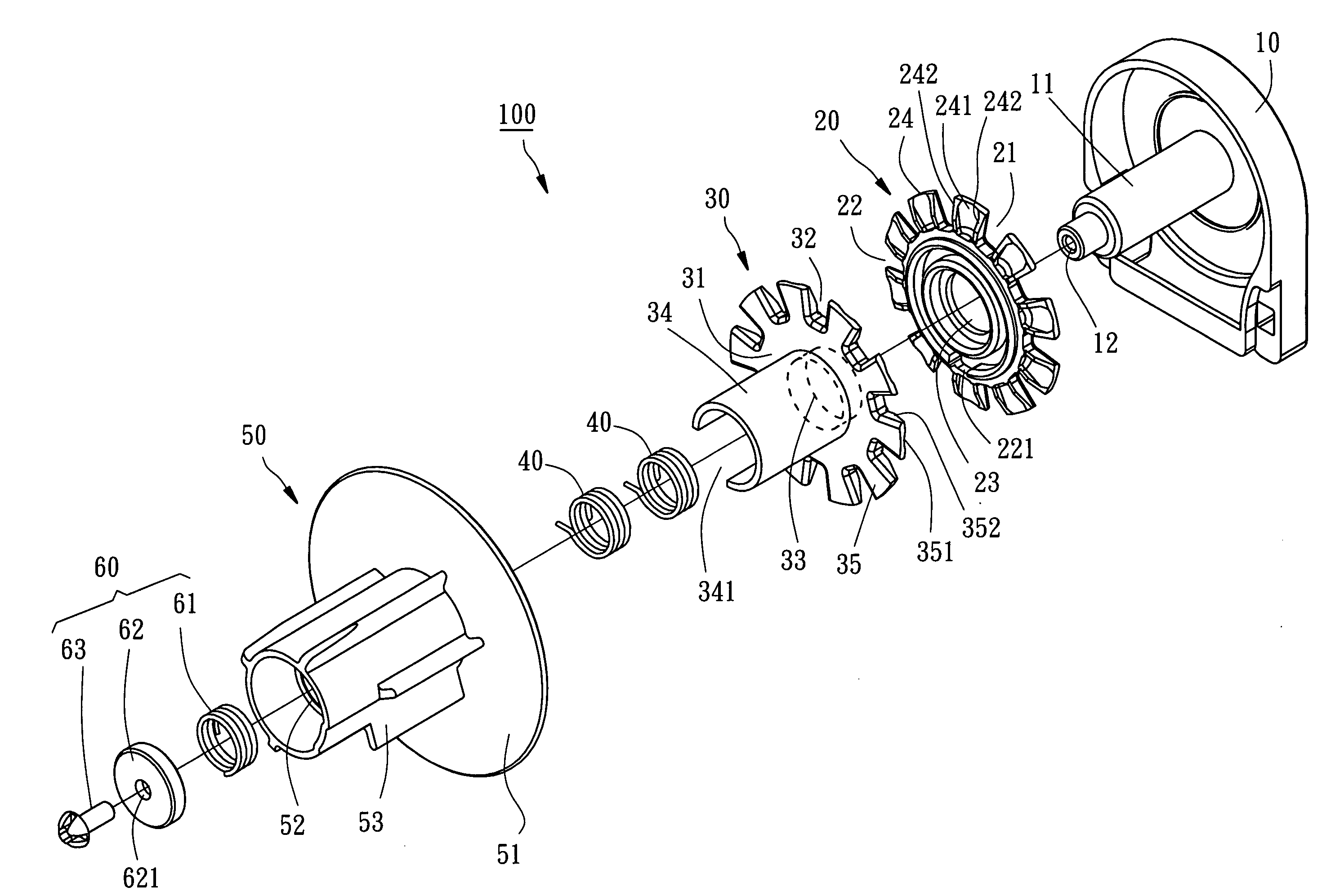
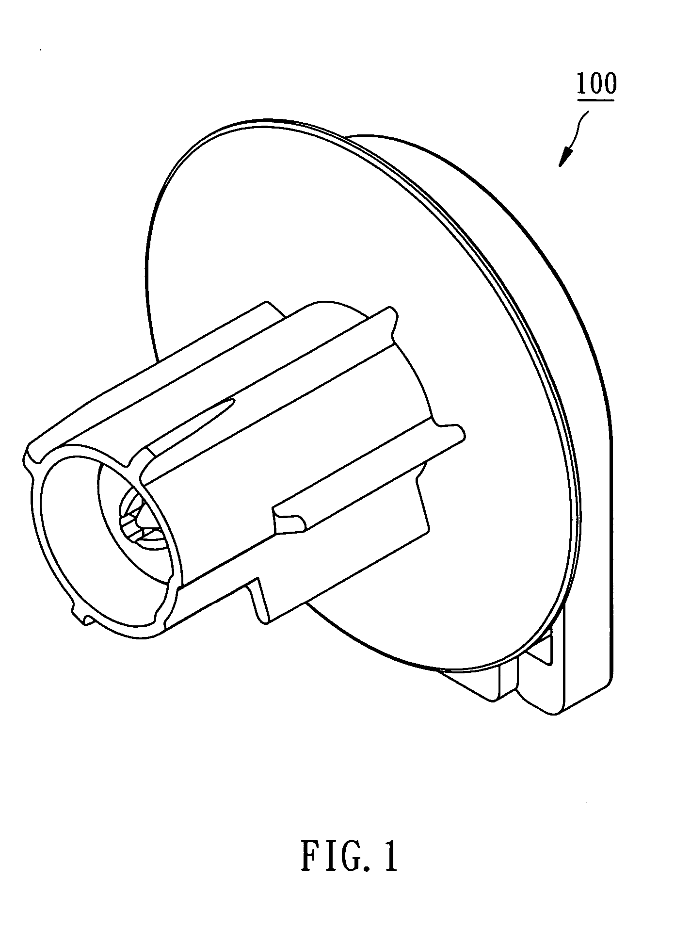
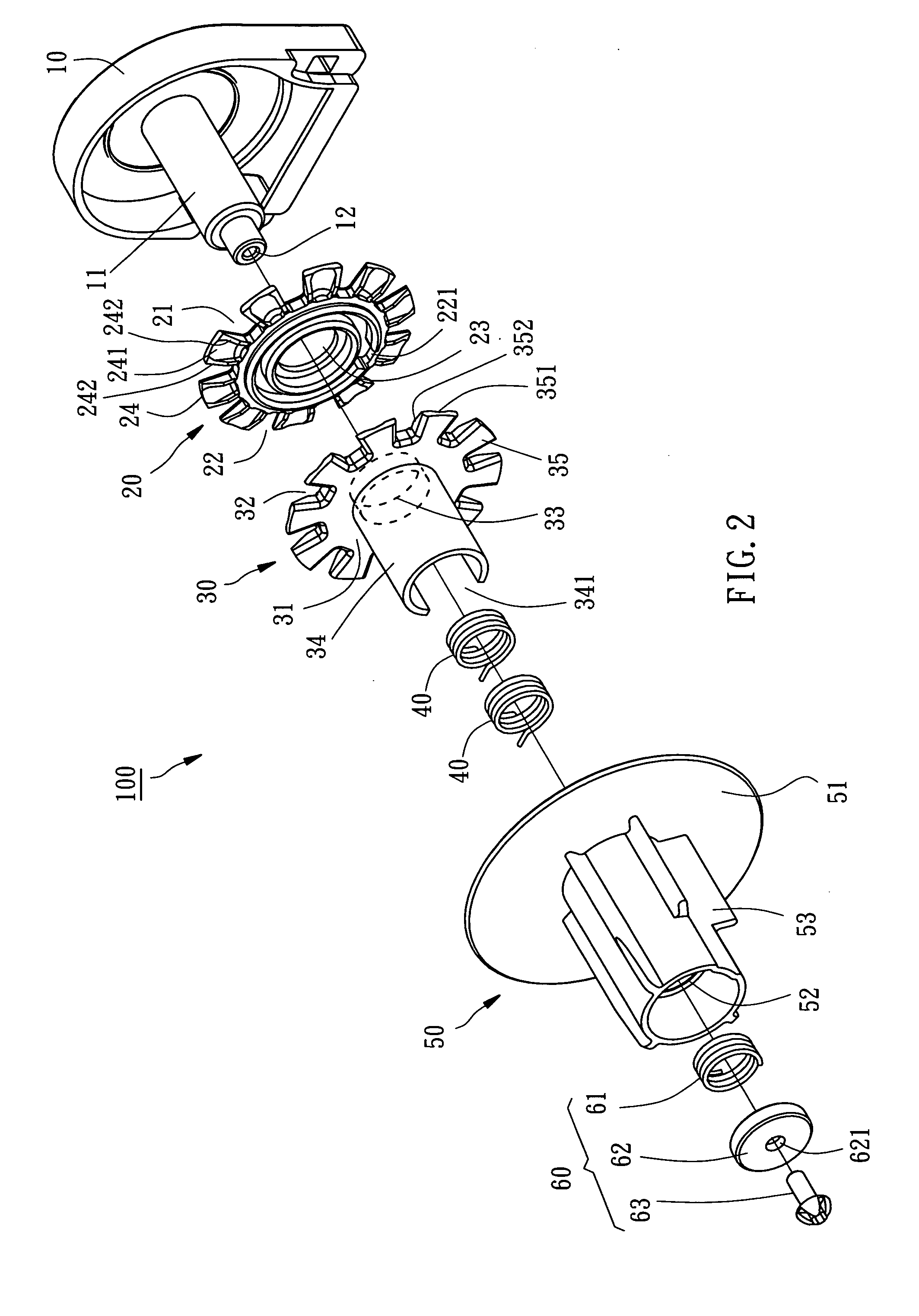
[0019]Referring to FIGS. 1–4, a cord-driven rotator 100 according to the first preferred embodiment of the present invention is shown comprised of a base 10, a first clamping plate 20, a second clamping plate 30, two positioning members 40, a hub 50, and an elastic biasing device 60.

[0020]The base 10 comprises a shaft 11, which has a screw hole 12 axially extended in the distal end.

[0021]The first clamping plate 20 is shaped like a circular member having a stop face 21, a clamping face 22 opposite to the top face 21, a center axle hole 23 cut through the stop face 21 and the clamping face 22 at the center and coupled to the shaft 11 of the base 10 to let the stop face 21 be set in close contact with the inside wall of the base 10, a coupling groove 221 formed in the clamping face 22, and a plurality of fins 24 equiangularly spaced around the periphery. The fins 24 each have a radially extended groove 241 corresponding to the clamping face 22, and two sloping edges 242 radially exten...


PUM


Abstract

A rotator, which is driven by an endless cord member to rotate, is used in a window blind for driving a roller of the window blind. The rotator includes a base having a shaft, a first clamping plate and a second clamping plate rotatably serially mounted on the shaft of the base for clamping the cord member therebetween, and an elastic biasing device provided between the base and one of the first and second clamping plates for urging the first and second clamping plates against each other.

Description

[0001]This Non-provisional application claims priority under 35 U.S.C. § 119(a) on patent application Ser. No(s). 093207201 filed in Taiwan, Republic of China on May 7, 2004, the entire contents of which are hereby incorporated by reference.BACKGROUND OF THE INVENTION[0002]1. Field of the Invention[0003]The present invention relates to generally to a rotator, which is connected with and driven by an endless cord member, for use in a window blind for driving a roller around which a blind shade is wound, and more particularly to such a cord-driven rotator, which has a cord member clamping function that prevents the cord member from slipping relative to the rotator.[0004]2. Description of the Related Art[0005]A conventional cord-driven rotator for use in a lifting window blind or the like is known comprising a base, which has a shaft, a friction wheel, which is pivoted to the shaft and has a V-shaped groove extended around the periphery, and an axle sleeve sleeved onto the shaft and co...

Claims


Application Information

Patent Timeline
Patent Type & Authority Patents(United States)
IPC IPC(8): E06B9/56A47H3/02B25B1/22E06B9/42E06B9/78
CPCE06B9/42
Inventor NIEN, MINGWEN, YUCHECHANG, CHIH-YAO
Owner NIEN MADE ENTERPRISE CO LTD
Why Eureka
Try Eureka