View dependent displacement mapping

a technology of displacement mapping and view, applied in the field of computer generated graphics, can solve the problems of complex visual effects including fine-scale shadowing, occlusion, difficult to render efficiently, and limited performance for mesostructure rendering, and achieve the effect of quick and/or efficient us

Active Publication Date: 2007-03-27
MICROSOFT TECH LICENSING LLC
View PDF0 Cites 7 Cited by
  • Summary
  • Abstract
  • Description
  • Claims
  • Application Information

AI Technical Summary

Problems solved by technology

The high-frequency visible geometry of mesostructure leads to complex visual effects including fine-scale shadowing, occlusion and silhouettes.
These characteristics each contribute to realistic appearance, but are also difficult to render efficiently.
In addition, although conventional displacement mapping can be implemented in hardware, its performance for mesostructure rendering is limited by the large number of vertices that result from the considerable mesh subdivision required.
Although characteristics such as shading, self-shadowing and occlusion are realized, silhouette characteristics are lacking.

Method used


Image

  • View dependent displacement mapping
  • View dependent displacement mapping
  • View dependent displacement mapping

Examples


Embodiment Construction

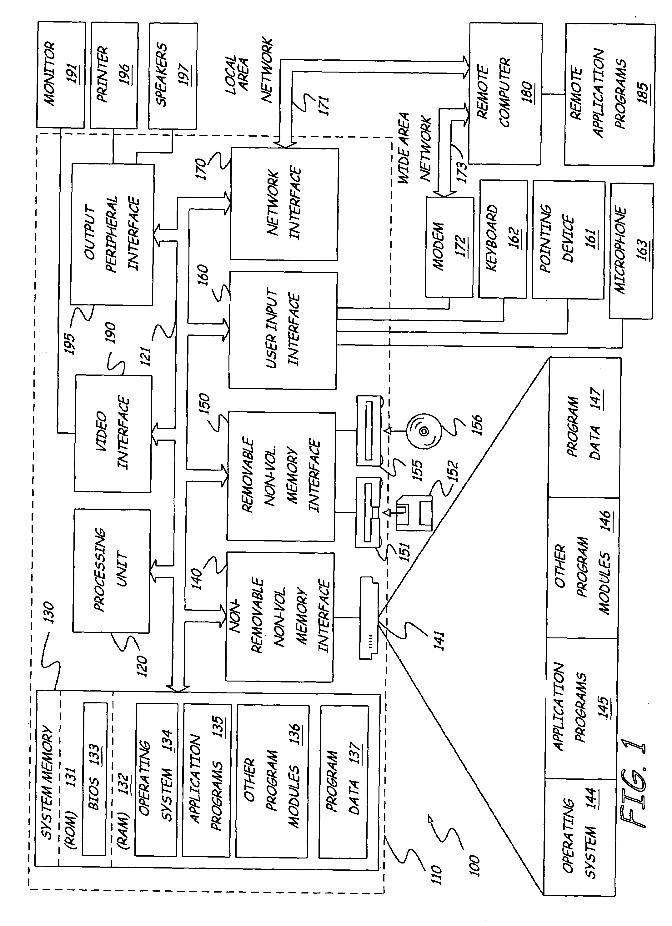
[0016]Prior to discussing the present invention in greater detail, an embodiment of an illustrative environment in which the present invention can be used will be discussed. FIG. 1 illustrates an example of a suitable computing system environment 100 on which the invention may be implemented. The computing system environment 100 is only one example of a suitable computing environment and is not intended to suggest any, limitation as to the scope of use or functionality of the invention. Neither should the computing environment 100 be interpreted as having any dependency or requirement relating to any one or combination of components illustrated in the exemplary operating environment 100.

[0017]The invention is operational with numerous other general purpose or special purpose computing system environments or configurations. Examples of well known computing systems, environments, and / or configurations that may be suitable for use with the invention include, but are not limited to, per...


PUM


Abstract

A computer implemented method for generating a representation of structure for use in rendering a synthesized image is provided. The representation is a view-dependent displacement mapping that represents displacements along a viewing direction. This view dependency allows the representation to be used to determine self shadows as well as shading, occlusion and silhouettes when used during rendering for synthesis.

Description

BACKGROUND OF THE INVENTION[0001]The present invention relates to computer generated graphics, in particular, the modeling and rendering of realistic graphics, focusing on fine-scale geometric features and associated visual effects of such features.[0002]Computer graphics are used in many different applications including computer games, movies and web pages. With the capability of more powerful computers, realistic graphics are becoming more desired in order to provide a more realistic experience to the computer user.[0003]Accurate computer rendering of fine-scale geometric features and associated visual effects yields vivid object appearance. This level of detail, commonly referred to as mesostructure, lies between that of meshes, which provide an efficient representation of gross shape, and bi-directional reflectance functions (BRDFs) that describe the light scattering effects of micro-scale material structure. The high-frequency visible geometry of mesostructure leads to complex ...

Claims


Application Information

Patent Timeline
Patent Type & Authority Patents(United States)
IPC IPC(8): G09G5/00G06T15/20
CPCG06T15/04
Inventor WANG, LIFENGWANG, XITONG, XINGUO, BAININGSHUM, HEUNG-YEUNG
Owner MICROSOFT TECH LICENSING LLC
Why Eureka
Try Eureka