High-resolution magnetoencephalography system, components and method

a magnetoencephalography and high-resolution technology, applied in the field of medical diagnostic systems and methods, can solve the problems of difficult maintenance of the gap or spacing between the head and the sensor, large and heavy size of the meg system,

Inactive Publication Date: 2007-03-27
TRISTAN TECH
View PDF15 Cites 78 Cited by
  • Summary
  • Abstract
  • Description
  • Claims
  • Application Information

AI Technical Summary

Problems solved by technology

Prior known MEG systems (such as those manufactured by Canadian Thin Films or CTF, Vancouver, Canada, 4-D Neuroimaging, San Diego, Calif., and Helsinki, Finland) are relatively large and heavy, and are used mostly in an expensive magnetically shielded room.
Due to the different coefficients of thermal expansion of the various components, this gap or spacing between the head and the sensors may be difficult to maintain in the presence of temperature changes for certain applications.
Also, when the dewar is cooled to its cryogenic temperatures, the components tend to change dimensionally for some applications.

Method used


Image

  • High-resolution magnetoencephalography system, components and method
  • High-resolution magnetoencephalography system, components and method
  • High-resolution magnetoencephalography system, components and method

Examples


Embodiment Construction

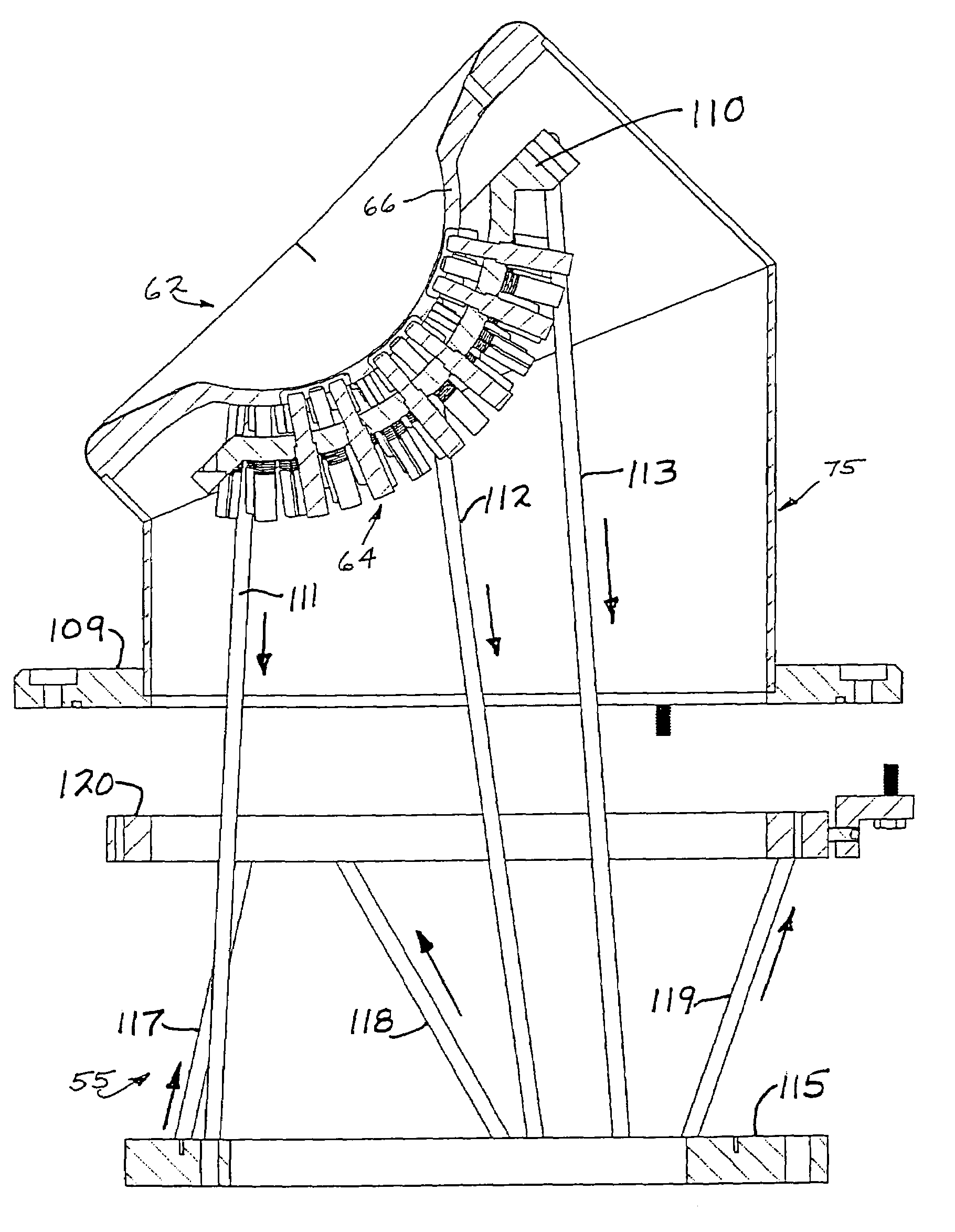
[0087]According to certain embodiments of the present invention, there is provided a mounting arrangement for a magnetoencephalography (MEG) system headrest assembly forming a portion of a SQUID dewar and having a fixed headrest and an array of sensors, wherein a sensor array plate positions the sensors relative to the headset. A plurality of first rods interconnecting the array plate and the movable mounting member. A plurality of second rods are fixed at one of their ends relative to the dewar and are connected at their opposite ends to the movable mounting member. Each one of the first and second rods is composed of material expandable and contractible with changes in temperature, whereby the movable mounting member tends to be moved in one direction toward or away from the sensor array plate, and tends to be moved in an opposite direction away from or toward the array plate, resulting in temperature changes affecting the first and second rods, so that the sensor array plate and ...


PUM


Abstract

According to certain embodiments of the present invention, there is provided a mounting arrangement for a magnetoencephalography (MEG) system headrest assembly forming a portion of a SQUID dewar and having a fixed headrest and an array of sensors, wherein a sensor array plate positions the sensors relative to the headset. A plurality of first rods interconnecting the array plate and the movable mounting member. A plurality of second rods are fixed at one of their ends relative to the dewar and are connected at their opposite ends to the movable mounting member. Each one of the first and second rods is composed of material expandable and contractible with changes in temperature, whereby the movable mounting member tends to be moved in one direction toward or away from the sensor array plate, and tends to be moved in an opposite direction away from or toward the array plate, resulting in temperature changes affecting the first and second rods, so that the sensor array plate and its sensors maintain a substantially constant spacing between the sensors and the headrest with changes in temperature. A plurality of second rods are fixed at one of their ends relative to the dewar and are connected at their opposite Each one o the rods is composed of material expandible and contractable with changes in temperature, whereby the movable mounting member tends to be moved in one direction toward or away from the sensor array plate, and tends to be moved in an opposite direction away from or toward the array plate resulting in temperature changes affecting the first and second rods, so that the sensor array plate and its sensors maintain a substantially constant spacing between the sensors and and headrest with changes in temperature.

Description

RELATED APPLICATIONS[0001]The present application is a continuation-in-part patent application, entitled SELF-ADJUSTING ASSEMBLY AND METHOD FOR CLOSE TOLERANCE SPACING, Ser. No. 10 / 228,694, filed Aug. 26, 2002 now U.S. Pat. No. 6,784,663, which is incorporated herein by reference, and is related to U.S. patent application entitled HIGH-RESOLUTION MAGNETOENCEPHALOGRAPHY SYSTEM AND METHOD, Ser. No. 10 / 609,259, filed Jun. 26, 2003, which is also incorporated herein by reference.BACKGROUND OF THE INVENTION[0002]1. Field of the Invention[0003]The invention relates to medical diagnostic systems and methods. In particular, the invention relates to a system and method for obtaining high-resolution encephalographs.[0004]2. Related Art[0005]The information contained in this section relates to the background of the art of the present invention without any admission as to whether or not it legally constitutes prior art.[0006]The following is a list of articles relating to various diagnostic tec...

Claims


Application Information

Patent Timeline
Patent Type & Authority Patents(United States)
IPC IPC(8): A61B5/05G01R33/035
CPCG01R33/0354
Inventor GOTT, SHELDON J.MASCARENAS, ANTHONY D.REINEMAN, RICHARD CHARLES
Owner TRISTAN TECH
Why Eureka
Try Eureka