Fluid-filled vibration damping device

a technology of vibration damping device and fluid filling, which is applied in the direction of shock absorbers, machine supports, jet propulsion mountings, etc., can solve the problems of noise or vibration, and the fluid filling vibration damping device may generate noise or vibration, and achieve the effect of effectively utilizing pinholes and minimizing the transmission of jet flow energy during bursting

Inactive Publication Date: 2007-04-03
SUMITOMO RIKO CO LTD
View PDF21 Cites 2 Cited by
  • Summary
  • Abstract
  • Description
  • Claims
  • Application Information

AI Technical Summary

Benefits of technology

[0032]According to this mode, the cushion member is elastically supported by the partition member via the annular elastic support projection in a consistent manner, so that transmission of jet flow energy caused by bursting of the bubbles to the external area via the cushion member is advantageously prevented with the help of vibration isolating function of the annular elastic support projection. Further, since the elastic support projection is bonded to the surface of the partition member facing to the pressure-receiving chamber such that the elastic support projection extend circumferentially at a circumferential portion of the surface of the partition member, the vibration isolating function of the elastic support projection is exhibited to the partition member, further minimizing transmission of the jet flow energy during bursting of the bubbles to the external area through the partition member.
[0033]A tenth mode of the invention provides a fluid-filled vibration-damping device according to the ninth mode, wherein the annular elastic support projection includes a plurality of pinholes open in the projecting end face thereof at respective circumferential positions, which is formed by means of positioning pins for positioning the partition member within a mold cavity for forming the annular elastic support projection, and the cushion member includes a plurality of engaging pins projecting outward from one of opposite surfaces thereof at respective circumferential positions corresponding to that of the pinholes, the plurality of engaging pins of the cushion member being brought into press fit engagement with the plurality of pinholes of the annular elastic support projections, respectively. This arrangement makes it possible to fasten the cushion member to the partition member by means of a simple fastening structure that is produced by effectively utilizing pinholes formed in the elastic support projection upon forming thereof.

Problems solved by technology

An extensive study and analysis conducted by the inventors on these conventional fluid-filled vibration damping devices revealed that these conventional fluid-filled vibration damping devices may cause noises or vibrations in the event of input of a relatively large vibrational load between the first and second mounting members.
Specifically, when being employed as an engine mount in an automotive vehicle, the conventional fluid-filled vibration damping device may generate noises or vibrations large enough to be sensed by passengers in a cabin of the vehicle, if the vehicle runs across a wave-type road, or alternatively runs over a speed breaker or the like.

Method used


Image

  • Fluid-filled vibration damping device
  • Fluid-filled vibration damping device
  • Fluid-filled vibration damping device

Examples


Embodiment Construction

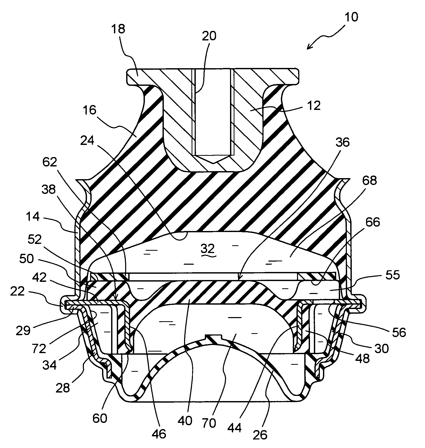
[0047]Referring first to FIG. 1, shown is a fluid-filled vibration-damping device in the form of an engine mount 10 for use in automotive vehicles, which is constructed according to a first embodiment of the invention. The engine mount 10 is of structure having a first mounting member 12 of metal, a second mounting member 14 of metal and a rubber elastic body 16 by which the first and second mounting member are elastically connected with each other. The first mounting member 12 is mounted on a power unit side, while the second mounting member 14 is mounted on a body side of an automotive vehicle, so that the power unit is mounted on the body of the vehicle in a vibration damping fashion, via the engine mount 10. In the following description, the vertical direction will be basically used to refer to the vertical direction as seen in FIG. 1, or approximately the vertical direction of the engine mount 10 installed on the vehicle as described above in which a vibrational load is primari...


PUM


Abstract

A fluid-filled vibration damping device including: a rubber elastic body elastically connecting a first and second mounting member and partially defining a pressure-receiving chamber filled with a non-compressible fluid; a flexible layer partially defining an equilibrium chamber filled with the non-compressible fluid; an orifice passage permitting a fluid communication between the pressure-receiving chamber and equilibrium chamber; and a cushion surface situated opposite to an opening of the orifice passage to the pressure-receiving chamber in a first direction of flow of the fluid into and out of the opening, with a predetermined distance therebetween, while extending in a second direction approximately perpendicular to the first direction.

Description

INCORPORATED BY REFERENCE[0001]The disclosure of Japanese Patent Application No. 2002-357899 filed on Dec. 10, 2002 including the specification, drawings and abstract is incorporated herein by reference in its entirety.BACKGROUND OF THE INVENTION[0002]1. Field of the Invention[0003]The present invention relates generally to fluid-filled vibration damping devices capable of exhibiting damping effect on the basis of flows of the fluid sealed therein, and more particularly to a fluid-filled vibration damping device suitably applicable to engine mounts or other mounts for use in automotive vehicles, for example.[0004]2. Description of the Related Art[0005]Rubber vibration-damping devices, typically including a first and a second mounting member elastically connected via a rubber elastic body, have been widely been used in a variety of fields, as vibration damping couplings or mounts to be interposed between two members of a vibration system. In an attempt to enhance vibration-damping ef...

Claims


Application Information

Patent Timeline
Patent Type & Authority Patents(United States)
IPC IPC(8): F16F5/00F16F13/10F16F13/18F16F13/06
CPCF16F13/105B60K5/1283
Inventor NANNO, TAKANOBUINOUE, CHIYAKI
Owner SUMITOMO RIKO CO LTD
Why Eureka
Try Eureka