Chainsaw throttle and brake mechanisms

a technology of brake mechanism and chainsaw, which is applied in the field of chainsaws, can solve the problems of finger fatigue and shock to the finger squeezing the throttle trigger, chainsaws are potentially dangerous tools, and saw chain may be moving at a speed fast enough to be dangerous,

Inactive Publication Date: 2007-04-10
MYERS KENT J
View PDF16 Cites 9 Cited by
  • Summary
  • Abstract
  • Description
  • Claims
  • Application Information

AI Technical Summary

Benefits of technology

[0005]This invention provides advantages in a chainsaw comprising a brake drum; a saw bar; a saw chain disposed about said saw bar, wherein rotation of said brake drum at sufficient velocity causes said saw chain to be advanced about said saw bar; and a brake band disposed around said brake drum for braking the same. In accordance with this invention, the brake band includes a first movable end that is associated with a first biasing member and an independent second movable end that is biased by a second biasing member to draw said brake band against said brake drum and thereby prevent the rotation of said brake drum, i.e., chain run down. A throttle control trigger is operatively associated with said second movable end of said brake band and has an off throttle position and an on throttle position, wherein, when said throttle control trigger is moved from said off throttle position to said on throttle position, said second movable end moves against said second biasing member, thereby loosening said brake band from said brake drum and permitting the rotation of said brake drum, and, when said throttle control trigger is moved from said on throttle position to said off throttle position, said second movable end is moved by said second biasing member to draw said brake band against said brake drum and thereby prevent the rotation of said brake drum, i.e., chain run down.

Problems solved by technology

Chainsaws are potentially dangerous tools even when operators exercise extreme caution during their use.
This is known as “chain run down.” Even when the throttle is fully released, there is a chance that the saw chain may be moving at a rate fast enough to be dangerous.
It is believed that these attempts have failed, because they provided a chainsaw having a throttle that was too difficult to squeeze and keep depressed, causing finger fatigue and shock to the finger squeezing the throttle trigger, when the front hand guard is activated.

Method used


Image

  • Chainsaw throttle and brake mechanisms
  • Chainsaw throttle and brake mechanisms
  • Chainsaw throttle and brake mechanisms

Examples


Embodiment Construction

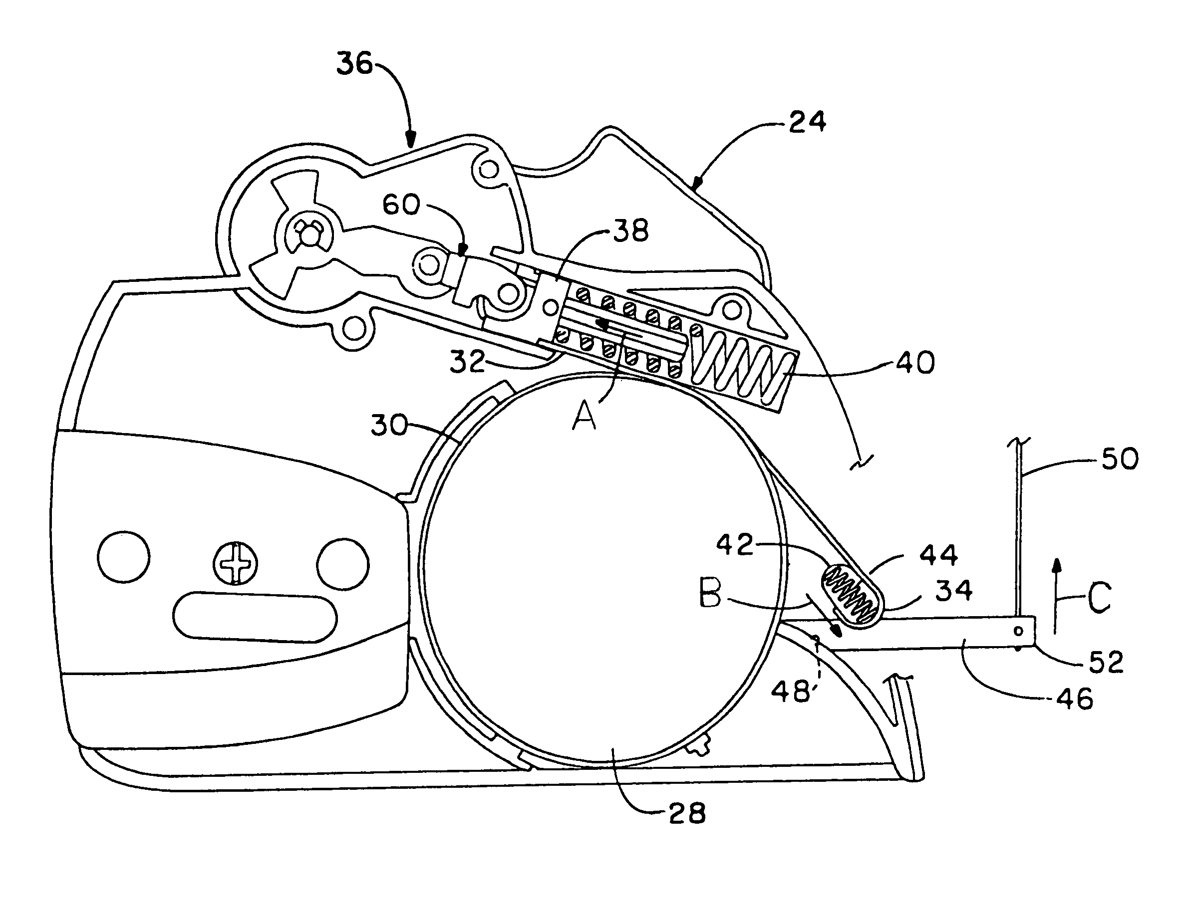
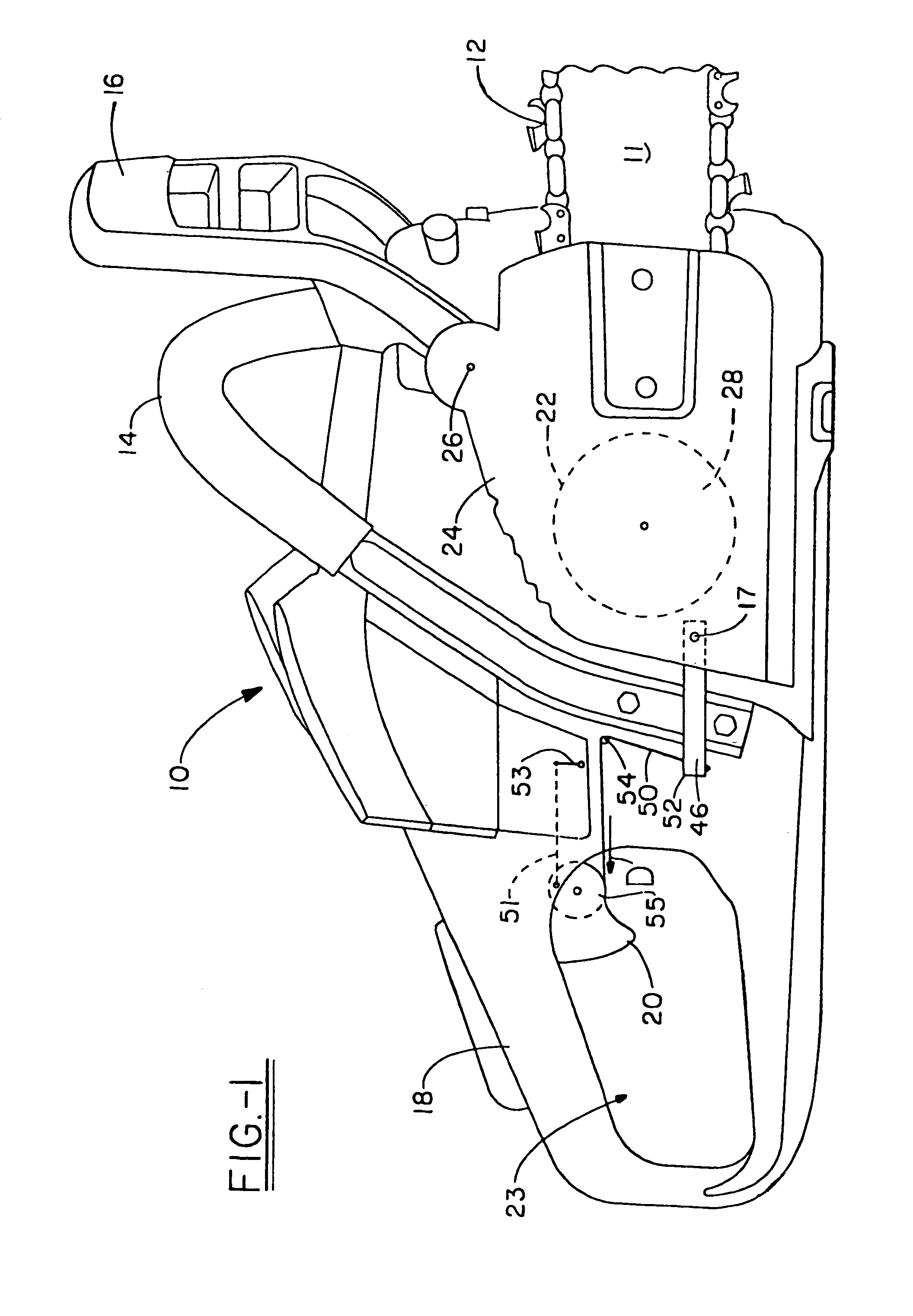
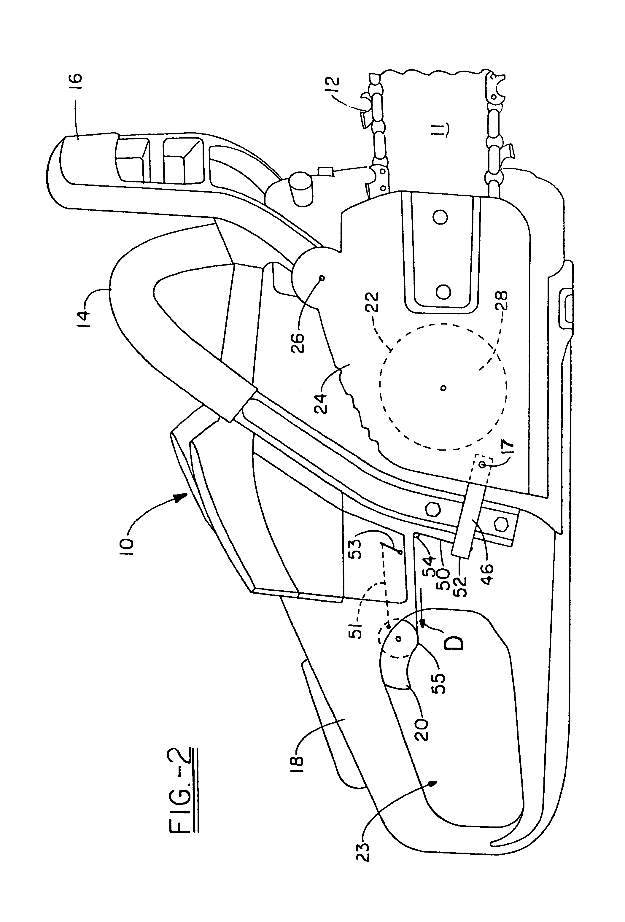
[0014]Referring now to FIG. 1, a chainsaw (or power saw) in accordance with this invention is shown and designated by the numeral 10. Chainsaw 10 includes saw bar 11, about which saw chain 12 rotates. Handle frame 14 is secured to the main body of chainsaw 10, with front hand guard 16 located in front of it. Rear handle 18 is provided for gripping chainsaw 10 and providing access to throttle control trigger 20, which is shown in the normal off throttle position, at handle opening 23. Component cover plate 24 covers and / or houses (explained below) components controlling the advancement of saw chain 12 about saw bar 11. Cover plate 24 also covers and / or houses braking mechanisms to control saw chain 12. These braking mechanisms are actuated by front hand guard 16, when it is moved forward about pivot point 26, whether by inertia or by contacting the operator's arm positioned at handle frame 14. This is all conventional and well-known prior art, and will be known to those of ordinary s...


PUM

PropertyMeasurementUnit
rotationaaaaaaaaaa
biasing forceaaaaaaaaaa
centrifugal forcesaaaaaaaaaa

Abstract

A chainsaw is provided having a brake band disposed about a drum that rotates during advancement of the saw chain about the saw bar. An end of the brake band is biased to a position that draws the brake band tight about the drum to prevent advancement of the saw chain, and the throttle trigger of the chainsaw is associated with this biased end to push the band against the bias and release the drum when the throttle trigger is squeezed to drive the elements of the chainsaw that serve to advance the saw chain. Also provided are new concepts for associating throttling and braking elements with the throttle trigger.

Description

TECHNICAL FIELD[0001]The present invention generally relates to chainsaws, and, more particularly, relates to braking mechanisms for providing added safety features to typical chainsaws. This invention is focused on handling chain run down.BACKGROUND ART[0002]Chainsaws are potentially dangerous tools even when operators exercise extreme caution during their use. Over the years, chainsaws have been manufactured to include braking mechanisms that are intended to function to stop the rotation of the saw chain about the saw bar in the event that the saw bar and the chain thereabout kick backwards toward the operator. These “kickback” brakes operate either through centrifugal forces or through impact of a front hand guard with the operator's support arm used to support and maneuver the chainsaw. In either case, the kickback brakes operate through the movement of various elements from active positions, where the saw chain is permitted to rotate about the chain guide, to brake positions, w...

Claims


Application Information

Patent Timeline
Patent Type & Authority Patents(United States)
IPC IPC(8): B23D57/02B60T13/04
CPCB27B17/083
Inventor MYERS, KENT J.
Owner MYERS KENT J
Why Eureka
Try Eureka