
Projector for defeating buried mines

a projector and mine technology, applied in the field of antimine systems, can solve the problems of complex disassembly and installation, inability to effectively and completely neutralize any mine, and inability to effectively and completely eliminate any mine, so as to minimize the likelihood of causing a sympathetic detonation, the effect of limited size and explosive

Active Publication Date: 2015-10-13
UNITED STATES OF AMERICA THE AS REPRESENTED BY THE SEC OF THE ARMY
View PDF6 Cites 4 Cited by
  • Summary
  • Abstract
  • Description
  • Claims
  • Application Information

AI Technical Summary

Benefits of technology

The present invention is an anti-mine device that uses a detonator to initiate a cylindrical mass of explosive, which in turn drives spherical hard fragments to neutralize antipersonnel mines. The device is designed to detonate at a distance from other mines to avoid a sympathetic detonation and minimize the likelihood of causing a soil shock wave. The detoinitation also expels overburden to provide a clear view of the mine for analysis and safe removal, and may uncover any other mines in a chain. The technical effects of this invention include effective and total neutralization of mines, minimization of hydrodynamic penetration, and the elimination of the need for subsequent uncovering of the disabled mines.

Problems solved by technology

While buried land mines were first developed in the late 19th century and became widely used in WWI, during the early 20th century, an effective system to disable them has proven elusive—as the earth within which they are buried provides significant protection thereof.
This difficulty in disabling such devices has been complicated with advances in the technology of the mines themselves; such as, blast resistant fusing, anti-handling features, and anti-tampering features.
The most reliable approach to demining is to layout a search grid and manually probed each grid point to find all possible threats; however, this is very manpower intensive and time consuming.
However, such alternative detection equipment has a halo of uncertainty, wherein the mine itself may be within a given radius vs. the exact spot that the equipment is indicating.
Or, alternatively, by simply placing a block of demolition charge in direct contact with the mine—trigger the fuze, or cause a sympathetic detonation of the explosive in the mine (and potentially other mines in the area—which may be dangerous to individuals in the vicinity).
Further, these method's generally require the mine's footprint to be positively ascertained, since pyrotechnic torches, shaped charge, or chemical means generally have a single vector of attack, which is limited in cross-section.
However, the limits of current detection equipment do not allow the precise determination of the mine footprint; but, only the location of the mine within the 4 inch radius halo of uncertainty.
Ensuring that a single vector defeat method contacts a buried mine within this halo is substantially more problematic in the case of small anti-personnel mines, which can be as small as 2 inches in diameter.
However, these darts in so traveling downwardly, perpendicular to face of the device, are limited in that they impact only a mine directly below the face of the device.
Therefore, unless the device has a face large enough to cover the halo of uncertainty, or if the mine is located directly under the face—the device will fail to neutralize the mine.
However, such irregular fragments produced by such a device would not effectively penetrate the overfill / overburden, and the device would have to be very large and heavy—to realize the desired effect.
Due to the emergence of increased usage of such smaller robotics in the demining mission, a neutralization tool deployed from such a robot must not exceed its limited payload capability; but, still cover the halo of uncertainty.

Method used


Image

  • Projector for defeating buried mines
  • Projector for defeating buried mines
  • Projector for defeating buried mines

Examples


Embodiment Construction

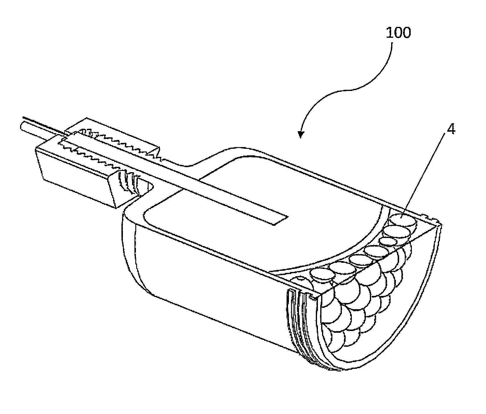
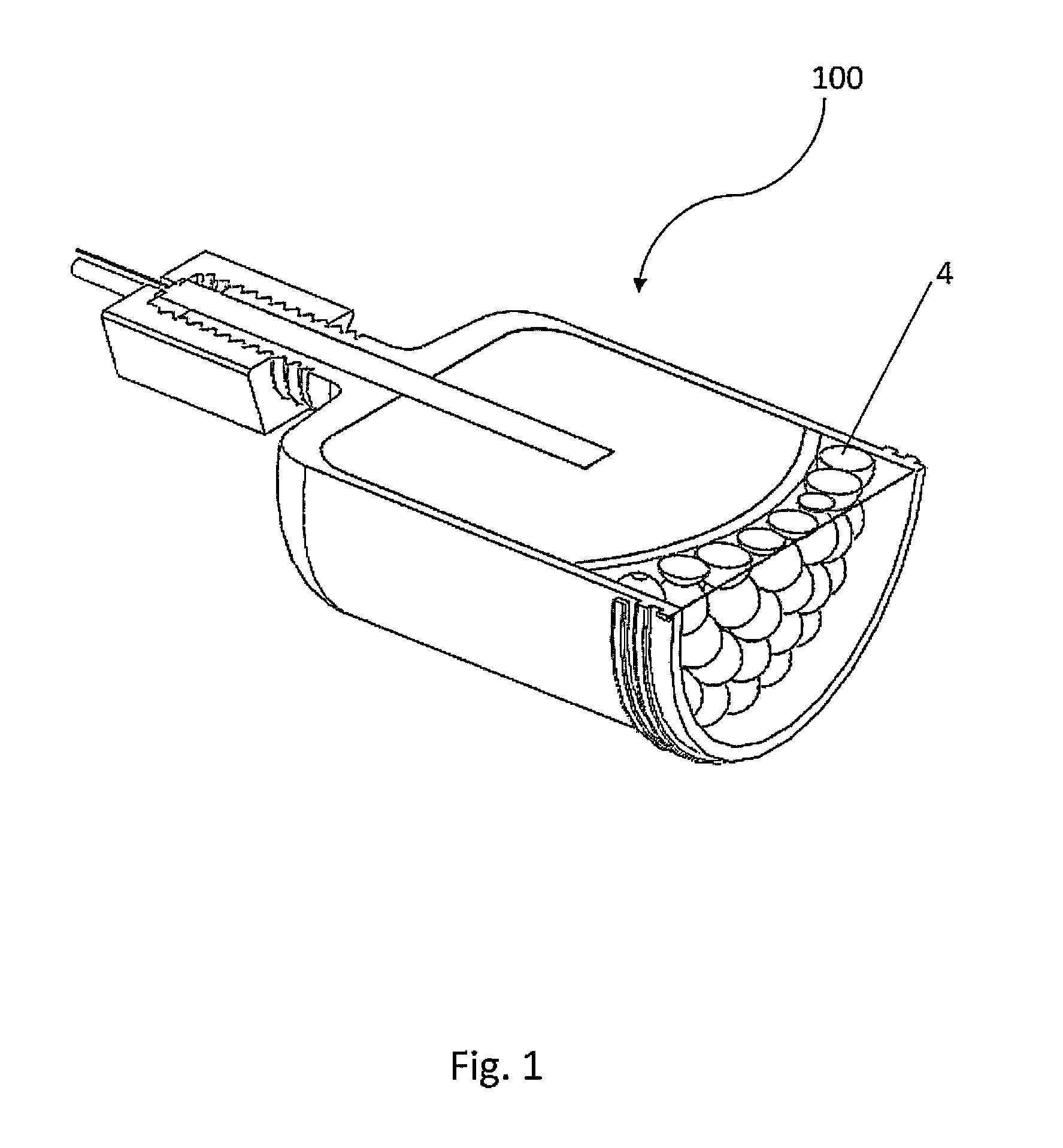
[0026]The invention, as embodied and described herein, and as shown in cut-away view in FIG. 1, is an explosively driven, fragment projecting anti-mine device (100), used for projecting an array of hard, spherical fragments (4), at a velocity within a specific range, over a specific area and through overfill (i.e. overburden) material, to effectively neutralize a buried anti-personnel mine, or other type of mine—wherein the relatively small and hard fragments do not spall, and wherein the size of the subject invention and quantity of explosive therein is such as to minimize and sympathetic explosions of other nearby mines. Further, the subject invention, as discussed herein, also surprisingly, blows the overburden from over the mine—to reveal it and aid in its safe removal.

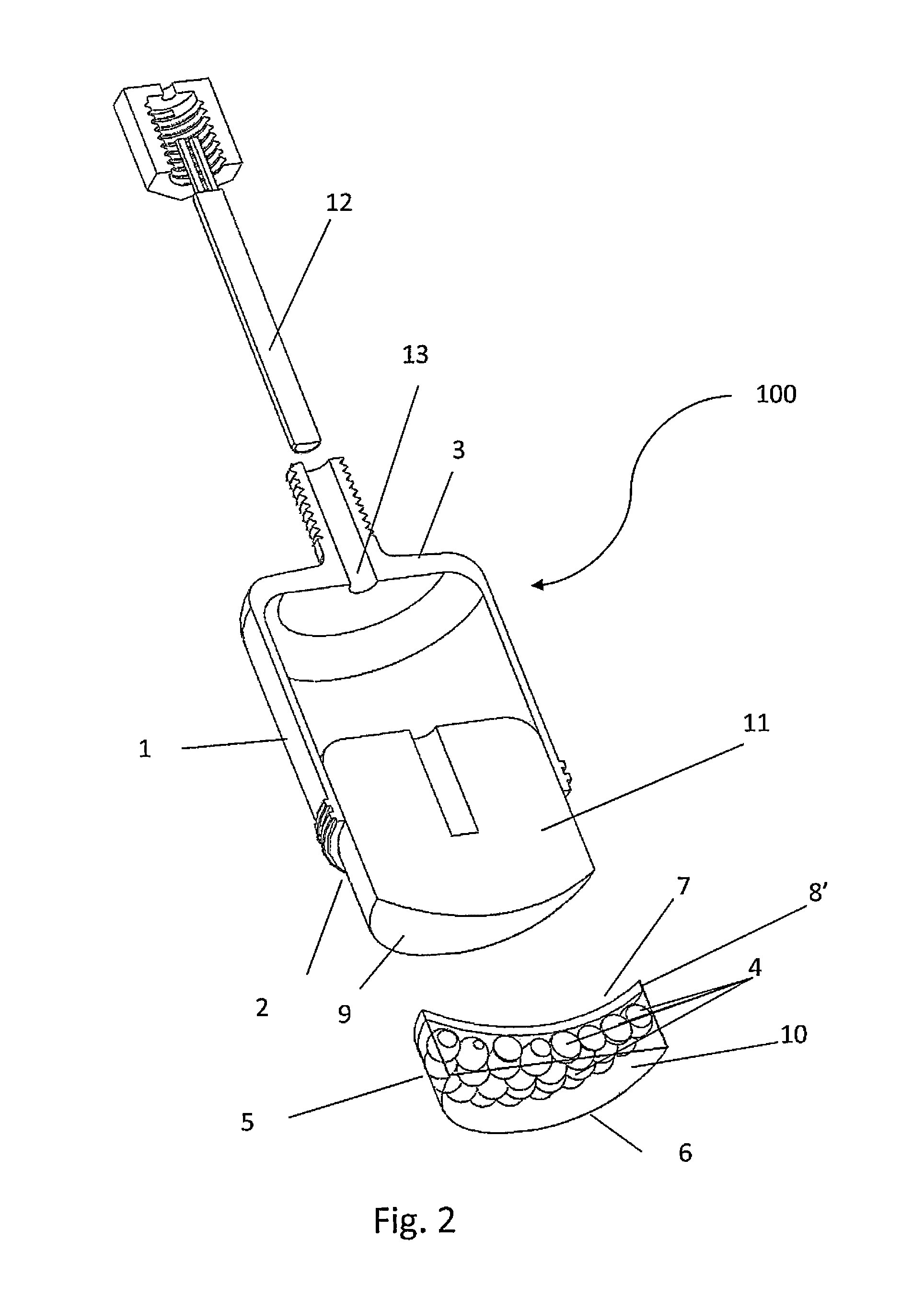
[0027]Referring to FIG. 2, an anti-mine fragment projecting device of the present invention (100), comprising a tubular housing (1) having an open end (2) and a closed end (3), a puck (5), which is a polymer matri...


PUM


Abstract

An relatively small anti-personnel mine device having a housing about 2 to about 3 inches in diameter, by about 2 to about 4 inches in length, which device projects a dispersion pattern of ⅛ to ⅜ inch diameter hard fragments over at least a 3 to 4 inch radius circle to neutralize a typical, buried, anti-personnel mine. The device contains about 125 to 190 grams of plastic explosive, which when detonated impacts a gas push plate against which an array of the fragments are lodged—the gas push plate and the fragments being encased in a puck shaped matrix of plastic or resin. The effect of the device is such that in addition to neutralizing the mine, the overburden atop the buried mine is expelled exposing the mine, providing enhanced safety in removal and a warning if the mine is daisy-chained to other mines.

Description

STATEMENT OF GOVERNMENT INTEREST[0001]The invention described herein may be manufactured, used, imported, sold, and / or licensed by or for the Government of the United States of America for U.S. Government purposes, without the payment or any royalty thereon or therefore.BACKGROUND OF THE INVENTION[0002]1. Field of the Invention[0003]The present invention relates to an anti-mine system capable of effectively neutralizing buried mines, and in particular, to such a system which is readily portable and can easily positioned by small to medium scale robots to defeat buried anti-personnel.[0004]2. Description of the Related Art[0005]While buried land mines were first developed in the late 19th century and became widely used in WWI, during the early 20th century, an effective system to disable them has proven elusive—as the earth within which they are buried provides significant protection thereof. This difficulty in disabling such devices has been complicated with advances in the technolo...

Claims


Application Information

Patent Timeline
IPC IPC(8): F41H11/12
CPCF41H11/12
Inventor MAJERUS, MARK E.VANAMAN, RICHARD L.BERGERIA, WILLIAM J.
Owner UNITED STATES OF AMERICA THE AS REPRESENTED BY THE SEC OF THE ARMY
Learn More