Ultrasonic miniature air gap inspection crawler

a miniature air gap and crawler technology, applied in the field of miniature robotic devices, can solve the problems of inability to meet the inspection task in a satisfactory manner, omission of generator and stator inspections from outage schedules, and time-consuming,

Active Publication Date: 2007-04-10
GENERAL ELECTRIC CO
View PDF20 Cites 48 Cited by
  • Summary
  • Abstract
  • Description
  • Claims
  • Application Information

AI Technical Summary

Problems solved by technology

The cost of the disassembly and the removal of the field, the time it takes for this process, and the dangers of field removal have led to the occasional omission of the generator and stator examinations from outage schedules.
These procedures have not accomplished t

Method used


Image

  • Ultrasonic miniature air gap inspection crawler
  • Ultrasonic miniature air gap inspection crawler
  • Ultrasonic miniature air gap inspection crawler

Examples


Embodiment Construction

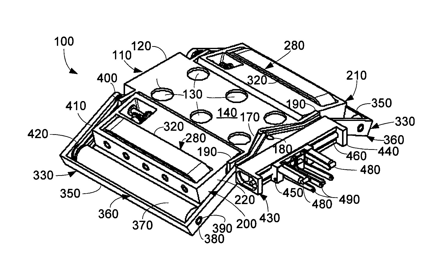
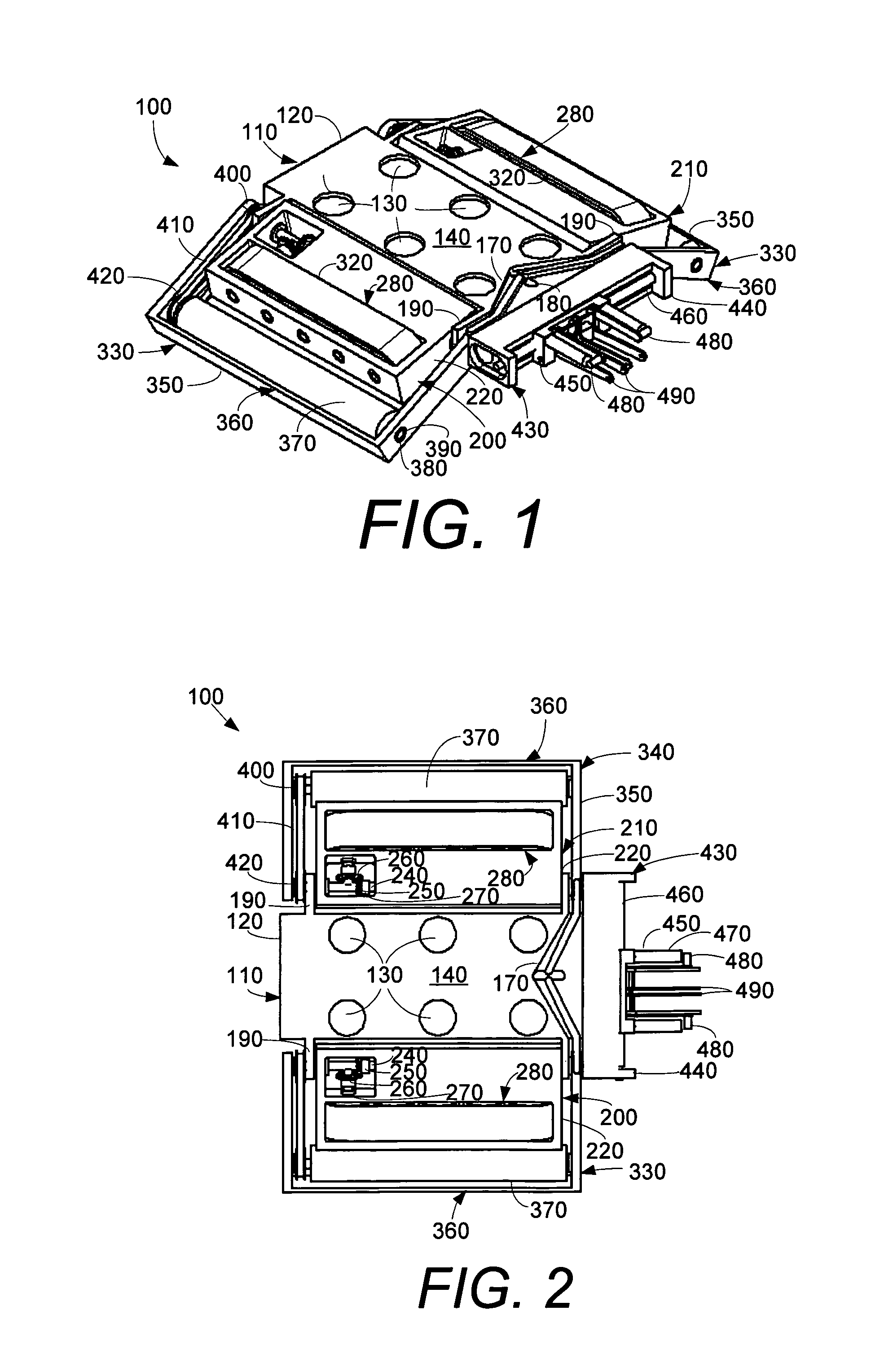
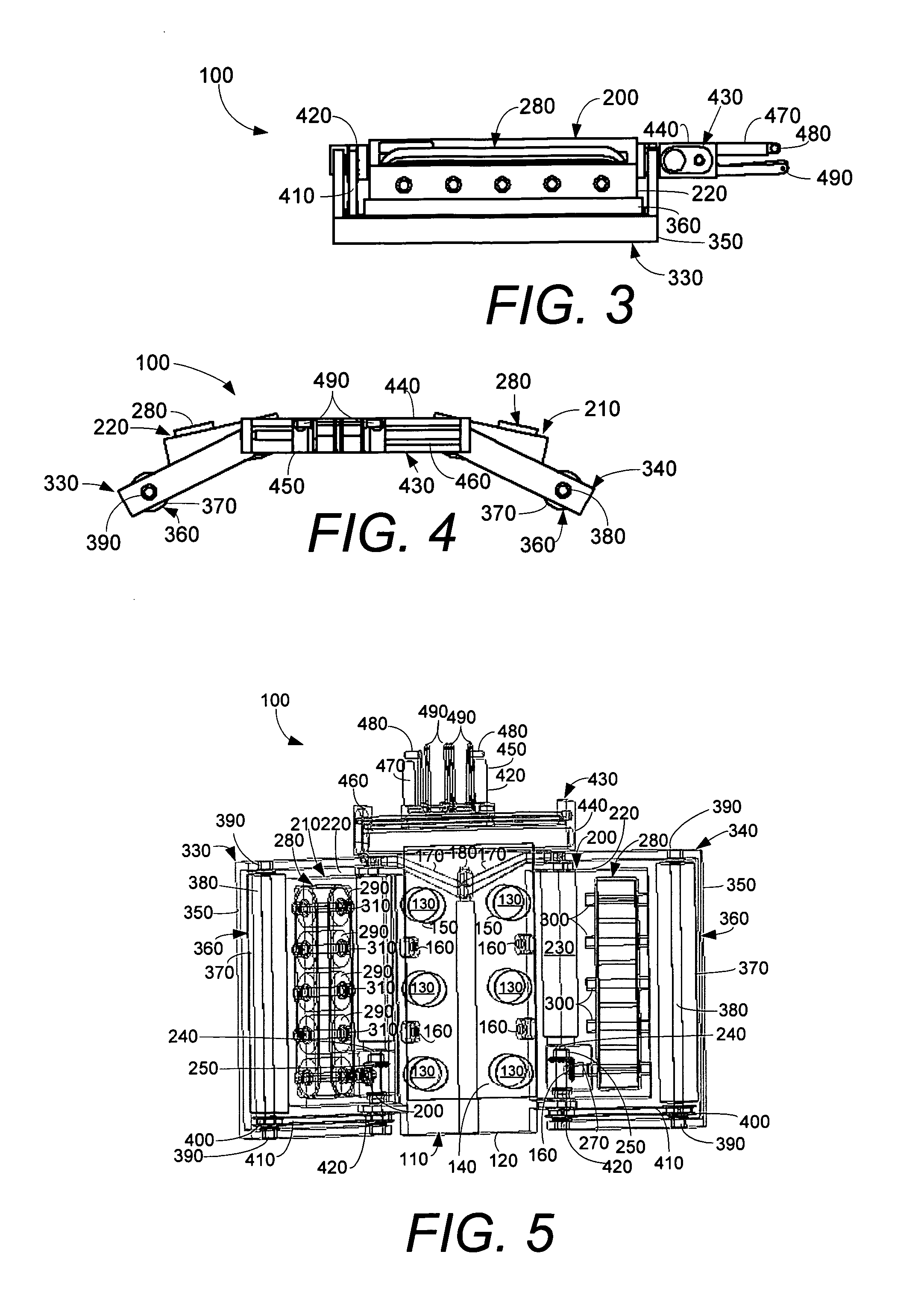
[0023]Referring now to the drawings, in which like numerals indicate like elements throughout the several views, FIGS. 1–6 show a miniature air gap inspection crawler 100 as is described herein. As described above, the crawler 100 may be dimensioned so as to fit within a typical radial air gap. The crawler 100 generally includes a number of individual modules or components as will be described in more detail below.

[0024]The crawler 100 may include a center module 110. The center module 110 may include a center body 120. The center body 120 may be largely rectangular in shape and substantially hollow so as to serve as a housing for the components described below. The center body 120 may be made out of aluminum, non-magnetic stainless steel, or similar types of materials.

[0025]Positioned within the center body 120 may be a number of magnets 130. The magnets 130 may be electromagnets or rare earth permanent magnets. Other types of magnetic devices or attachment devices also may be used...


PUM


Abstract

A miniature air gap inspection crawler. The miniature air gap inspection crawler may include a base, a linear drive mechanism and a circumferential drive mechanism such that either the linear drive mechanism or the circumferential drive mechanism may be employed, and an inspection module connected to the base.

Description

TECHNICAL FIELD[0001]The present invention relates generally to a miniature robotic device and more particularly relates to a miniature robotic device for performing in-situ ultrasonic inspections of a generator field.BACKGROUND OF THE INVENTION[0002]The visual inspection of a generator field and stator should be performed on a periodic basis. Conventional generator / stator inspection and testing procedures typically require the complete disassembly of the stator and the removal of the generator field from the stator before any inspections or tests can be performed on the unit. The cost of the disassembly and the removal of the field, the time it takes for this process, and the dangers of field removal have led to the occasional omission of the generator and stator examinations from outage schedules.[0003]In-situ inspections of generators have been performed employing poles, trolleys, and field turning techniques. These procedures have not accomplished the inspection task in a satisf...

Claims


Application Information

Patent Timeline
IPC IPC(8): G01N29/04G01M99/00
CPCG01R31/34H02K15/00
Inventor BAGLEY, PAUL C.HATLEY, RICHARDRONEY, ROBERT M.HATLEY, KENNETH
Owner GENERAL ELECTRIC CO
Why Eureka
Try Eureka