
Ultrasonic device for tissue ablation and sheath for use therewith

a tissue ablation and ultrasonic probe technology, applied in the field of shielded ultrasonic medical probes, can solve the problems of tissue fragmentation, tissue fragmentation or dissolution, and the ultrasonic probes described in the art for tissue ablation suffer from a number of limitations, so as to facilitate the penetration of antithrombogenic agents, prevent the recurrence of stenosis, and the precision control level

Inactive Publication Date: 2009-03-17
CYBERSONICS
View PDF883 Cites 387 Cited by
  • Summary
  • Abstract
  • Description
  • Claims
  • Application Information

AI Technical Summary

Benefits of technology

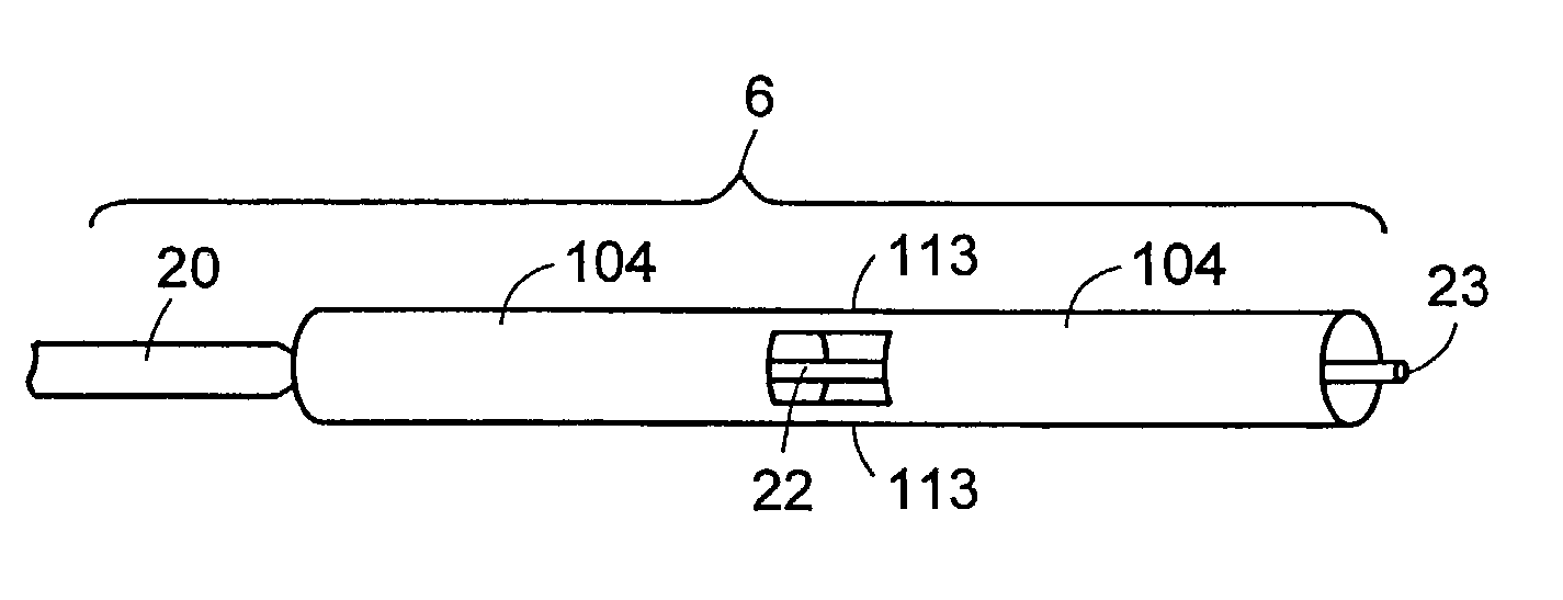
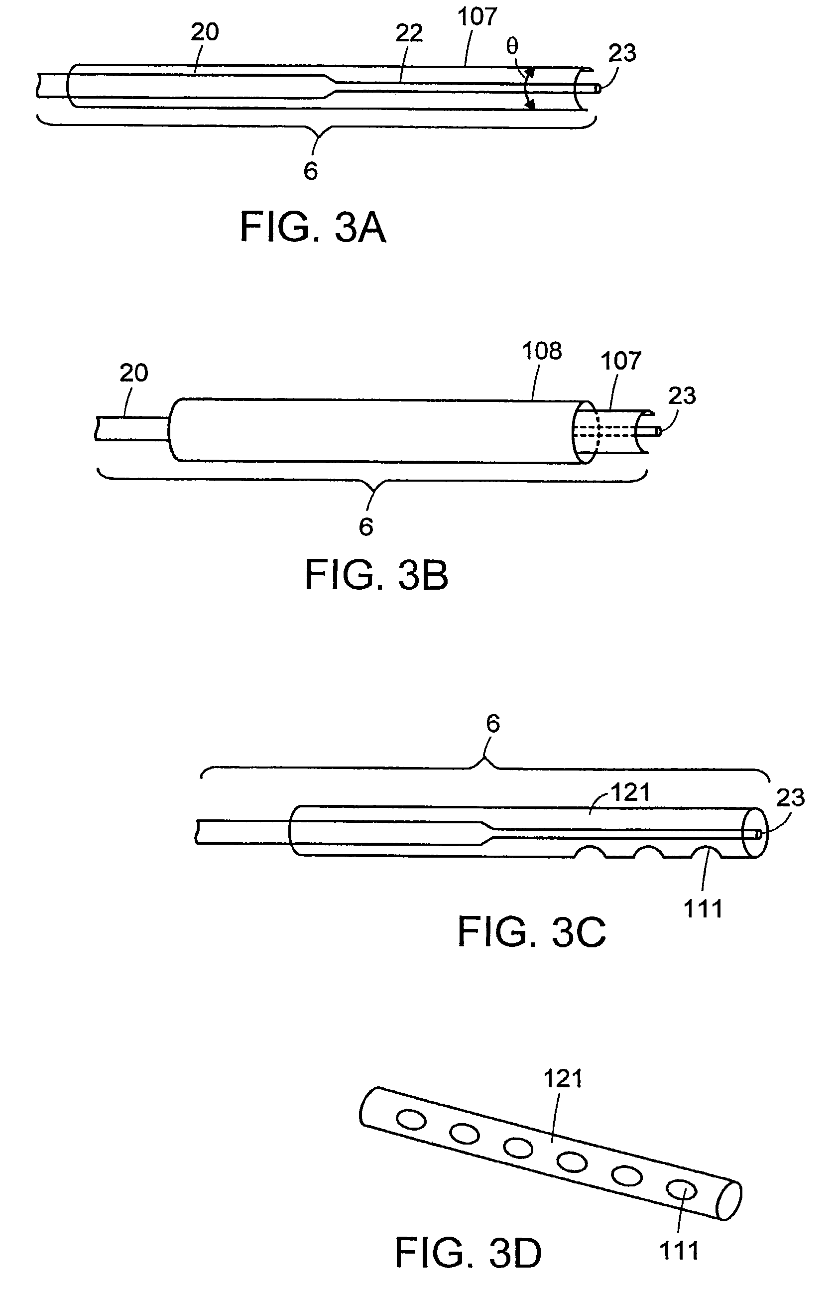
[0013]Further in accordance with the invention, a sheath, a sleeve or other damping member provided with fenestrations is a sheath that is adapted circumferentially along the probe axis, thereby providing control over release of cavitation energy in specific regions along the probe axis. Non-fenestrated areas of the said sheath or sleeve effectively block cavitation energy emanating from the probe from such areas.
[0015]In one aspect, a plurality of sheaths are used in combination to provide another level of precision control over the direction of cavitation energy to a tissue in the vicinity of the probe. In one embodiment of the invention, the sheath encloses a means of introducing fluid into the site of the procedure, and a means for aspirating fluid and tissue debris from the site of the procedure. In another aspect the sheath assembly further encloses a means of introducing a drug intravascularly that dissolves clots and prevents the recurrence of stenosis. The ultrasonic oscillation of the probe of the present invention will be used to facilitate the penetration of antithrombogenic agents into the vascular or luminal walls to inhibit restenosis. Preferred antithrombogenic agents include heparin, hirudin, hirulog, urokinase, streptokinase, tPA, and similar agents. In a further embodiment, the probe tip can be moved within the sheath. In yet another aspect, the irrigation and aspiration means, and the probe tip, can all be manipulated and repositioned relative to one another within the sheath. In another embodiment, the sheath is shaped in such a way that it may capture or grasp sections of tissue that can be ablated with the probe.
[0016]Still further in accordance with the invention, the sheath provides a guide for the probe tip, protecting tissues from accidental puncture by the sharp, narrow-diameter tip, or from destruction by energy emitted radially from the probe during introduction of the probe to the site. The sheath may be applied either to the probe tip prior to insertion of the probe into the patient, or pre-inserted into the patient prior to the insertion of the probe. The sheath of the present invention can be used to fix the location of one or more shapes relative to the nodes or anti-nodes of a probe acting in transverse action. The location of the reflective shapes can amplify the acoustical wave thereby magnifying the energy. This allows for the use of very small diameter probes which themselves would not have the requisite structural integrity to apply and translate acoustical energy into sufficient mechanical energy to enable ablation of tissues. The reflective shapes can also focus or redirect the energy, effectively converting a transverse probe emitting cavitation energy along its length, to a directed, side fire ultrasonic device.
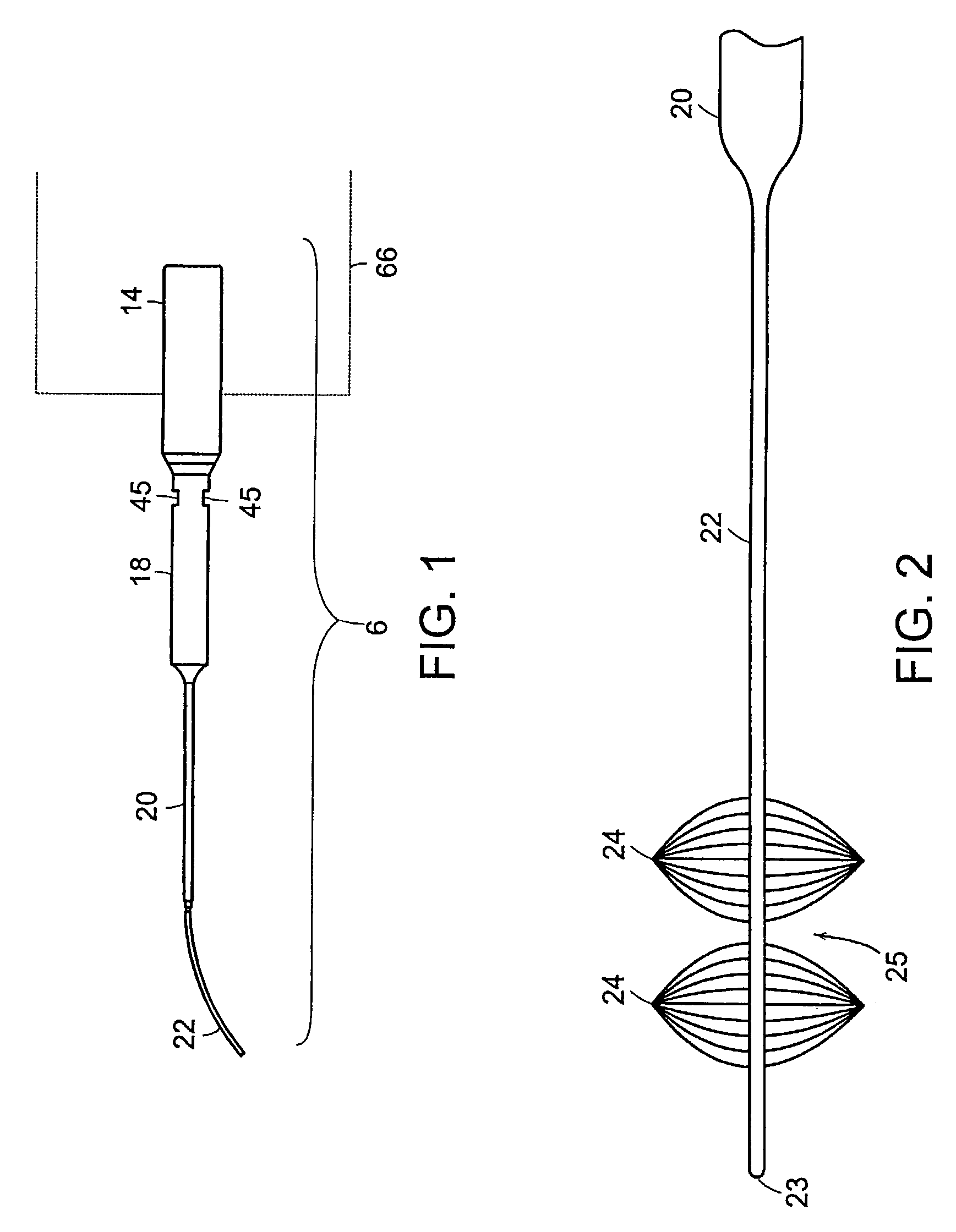
[0017]In a still further aspect of the invention the probe emits transverse ultrasonic energy along its longitudinal axis that may be used to, for example, fragment abnormal cells on the surface of the body cavity which come within the sweep of the probe, or to clear obstructions and constrictions within vasculature or tissue lumen. The device is designed to have a small cross-sectional profile, which also allows the probe to flex along its length, thereby allowing it to be used in a minimally invasive manner. In one aspect, the probe be at least partially contained within the sheath to contain, focus, intensify, and direct the emitted cavitation energy to specific target tissue sites. In another embodiment of the invention, a plurality of sheaths are used in combination to provide another level of precision control over the direction of cavitation energy to a tissue in the vicinity of the probe.
[0018]Still further in accordance with the invention, the sheath encloses a means of introducing fluid into the site of the procedure, and a means for aspirating fluid and tissue debris from the site of the procedure. In a further embodiment, the probe tip can be moved within the sheath. In one aspect, the irrigation and aspiration means, and the probe tip, can all be manipulated and repositioned relative to one another within the sheath. In another aspect, the sheath is shaped in such a way that it may capture or grasp sections of tissue that may be ablated with the probe. In yet another embodiment, the sheath provides a guide for the probe tip, protecting tissues from accidental puncture by the sharp, narrow diameter tip, or from destruction by energy emitted radially from the probe. The sheath may be applied to the probe tip prior to insertion of the probe into the patient, or the sheath can be inserted into the patient prior to the insertion of the probe.
[0019]The sheath of the present invention can be used to fix the location of one or more shapes relative to the energy nodes or anti-nodes emitted by a transversely vibrating probe. The location of and the particular shape can modulate the energy emitted from the probe at one site, and communicate it to a distant site, for example, it may amplify the acoustical wave at one or more energetic anti-nodes, thereby increasing the energy emitted at the sheath's aperture. This allows for the use of very small diameter probes which themselves would not have the requisite structural integrity to apply and translate acoustical energy into sufficient mechanical energy to enable ablation of tissues. The reflective shapes can also focus or redirect the energy, effectively converting a transverse probe emitting cavitation energy along its length, to for example, a directed, “side-fire” ultrasonic device.

Problems solved by technology

Typically, the energy produced by an ultrasonic probe is in the form of very intense, high frequency sound vibrations, results in fragmentation of tissue (plaque and thrombosis) either as a result of mechanical action thereon or “cavitation” thereof, in which high energy ultrasound frequency applied to liquids generates vapor-filled microbubbles or “cavities” with the concomitant rapid expansion and collapse of the cavities that is accompanied by intense localized hydraulic shock, that causes fragmentation or dissolution of the tissue.
Ultrasonic probes described in the art for tissue ablation suffer from a number of limitations.
i) tissue ablation is restricted to very small area defined by the surface area of the probe tip, thereby necessitating time consuming surgical procedures to remove relatively large occluded areas with blood vessels in comparison to instruments which excise tissue by mechanical cutting, electrocautery, or cryoexcision methods.
ii) occurrence of late restenosis (typically within three months), and to a lesser extent acute re-occlusion after coronary angioplasty are major clinical problems limiting the long-term efficacy of ultrasonic surgical procedures for treatment of atherosclerosis and coronary angioplasty.
Such post operative processes are typically result from localized trauma at the surgical site caused by mechanical and thermal action of longitudinally vibrating probes.
Thus, while destruction of tissue in proximity to the tip of the probe is more efficient, tissue destruction is still predominantly limited to the area in the immediate vicinity at the tip of the probe.
Although tissue destruction at the tip of the device is more efficient, the tissue destroying effect of the probe is still limited to the tip of the probe.
Both probes described in Kubota, et al., and Kelman, et al., are further limited in that the energy produced at the tip of the probe is unfocused, the action of the probe tends to push the tissue debris ahead of the probe tip.
Likewise, the concentration of energy solely at the probe tip results in heating of the probe tip, which can create tissue necrosis, thereby complicating the surgical procedure and potentially compromising the recovery of the patient.
Furthermore, such probes do not eliminate the problems associated with longitudinally vibrating probes.
Although narrow probe diameters are advantages especially for negotiation through narrow blood vessels and occluded arteries, the utilization of such probes have been precluded by inability to effectively control the vibrational amplitude of thin probes, that result in potential damage to the probe and greater risk, of tissue damage resulting from their use.

Method used


Image

  • Ultrasonic device for tissue ablation and sheath for use therewith
  • Ultrasonic device for tissue ablation and sheath for use therewith
  • Ultrasonic device for tissue ablation and sheath for use therewith

Examples


Embodiment Construction

[0030]The following terms and definitions are used herein:

[0031]“Anti-node” as used herein refers to a region of maximum energy emitted by an ultrasonic probe on or proximal to a position along the probe.

[0032]“Cavitation” as used herein refers to shock waves produced by ultrasonic vibration, wherein the vibration creates a plurality of microscopic bubbles which rapidly collapse, resulting in molecular collision by water molecules which collide with force, thereby producing the shock waves.

[0033]“Cross-sectional diameter” as used herein refers to the diameter of the cylindrical regions of the probe, including the probe tip.

[0034]“Fenestration” as used herein refers to an aperture, window, opening, hole, or space.

[0035]“Node” as used herein refers to a region of minimum energy emitted by an ultrasonic probe on or proximal to a position along the probe.

[0036]“Probe” as used herein refers to a device capable of being adapted to an ultrasonic generator means, which is capable of propaga...


PUM


Abstract

A transverse mode ultrasonic probe is provided which creates a cavitation area along its longitudinal length, increasing the working surface of the probe. Accessory sheaths are also provided for use with the probe to enable a user to select from features most suited to an individual medical procedure. The sheaths provide acoustic enhancing and aspiration enhancing properties, and / or can be used as surgical tools or as medical access devices, protecting tissue from physical contact with the probe.

Description

FIELD OF THE INVENTION[0001]The present invention relates generally to a shielded ultrasonic medical probe operating in a transverse mode for ablating and removing undesired tissue. In particular, the invention provides one or more acoustical sheaths for use with the probe, allowing the user to control and focus the energy emitted by the probe in a manner most suited to the desired medical procedure.BACKGROUND OF THE INVENTION[0002]Ultrasonic energy has been considered for tissue ablation and fragmentation of plaque and thrombosis for removal of intravascular occlusions due to atherosclerotic plaque and intravascular blood clots. Surgical devices utilizing ultrasonic probes for generation and transmission of ultrasonic energy, have been disclosed in the art (U.S. Pat. Nos. 5,112,300; 5,180,363; 4,989,583; 4,931,047; 4,922,902; and 3,805,787). Typically, the energy produced by an ultrasonic probe is in the form of very intense, high frequency sound vibrations, results in fragmentatio...

Claims


Application Information

Patent Timeline
IPC IPC(8): A61B8/00A61B8/14A61B17/50A61B17/00A61B17/22A61B17/28A61B17/32A61B18/00A61M1/00A61N7/02
CPCA61B17/22012A61N7/022A61B17/320068A61B2017/00137A61B2017/00274A61B2017/22002A61B2017/22007A61B2017/22008A61B2017/22015A61B2017/22018A61B2017/22051A61B2017/293A61B2017/320084A61B2017/320096A61B2018/00547A61B2018/00982A61B2217/005A61B2217/007A61M1/0084A61N2007/0008A61B2017/320098A61B2017/320069A61B2017/32007A61B2017/320089A61M1/85
Inventor RABINER, ROBERT A.HARE, BRADLEY A.
Owner CYBERSONICS
Learn More