Suspension storage rack

Active Publication Date: 2007-04-10
SUSPENZ
View PDF17 Cites 24 Cited by
  • Summary
  • Abstract
  • Description
  • Claims
  • Application Information

AI Technical Summary

Benefits of technology

[0027]The modular aspect of the structure provides an impor

Problems solved by technology

One shortcoming of prior art racks or shelves is that they are difficult to load and unload.
Many of the known storage racks are also of complex construction and thus are difficult to assemble an

Method used


Image

  • Suspension storage rack
  • Suspension storage rack
  • Suspension storage rack

Examples


Embodiment Construction

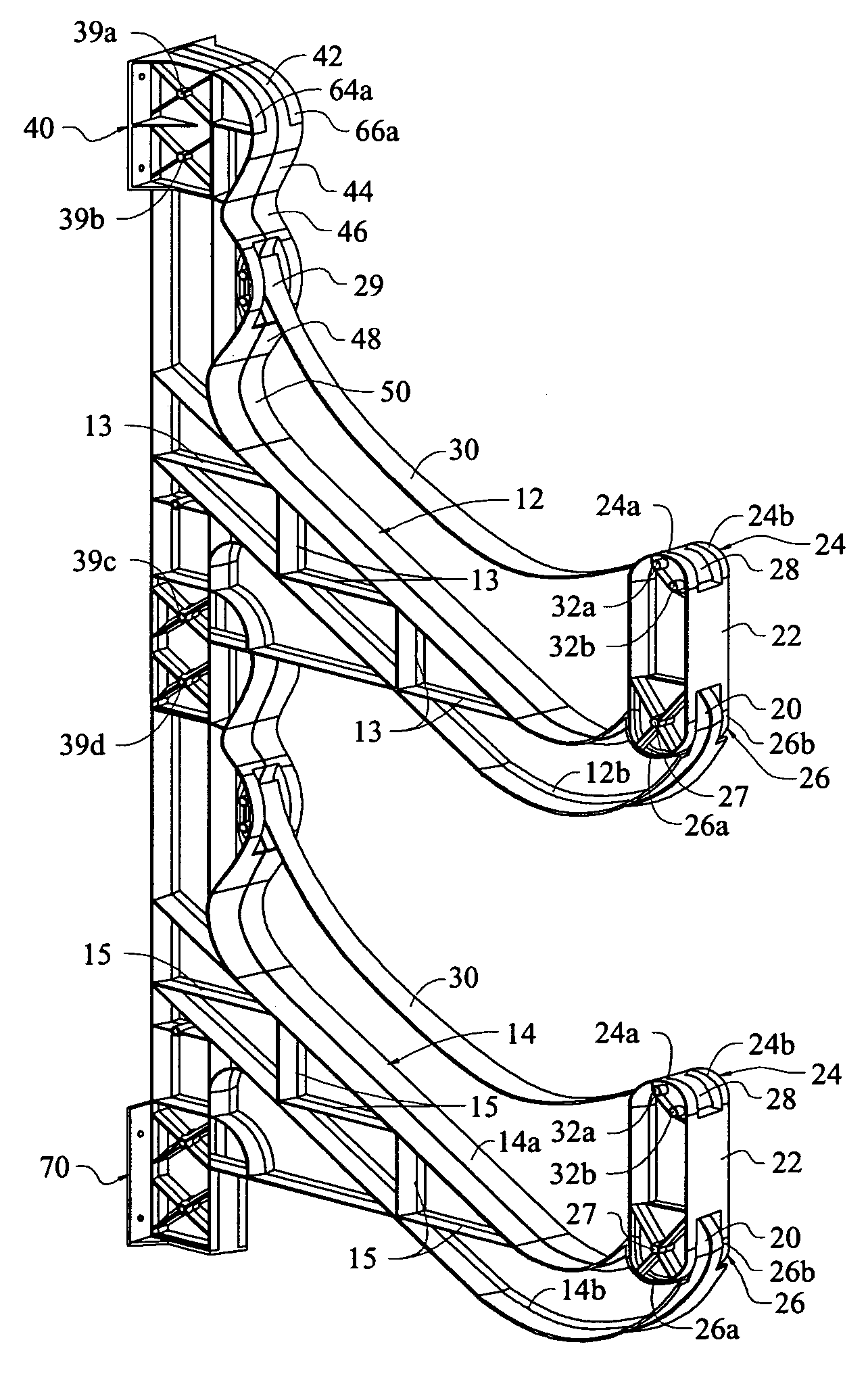
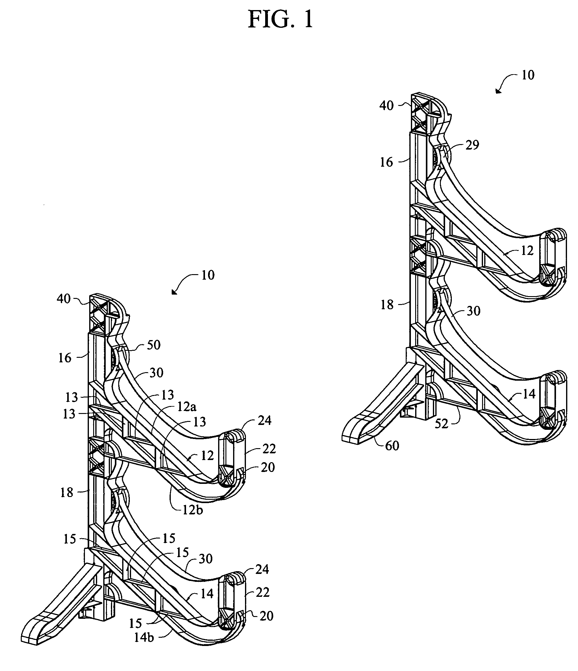
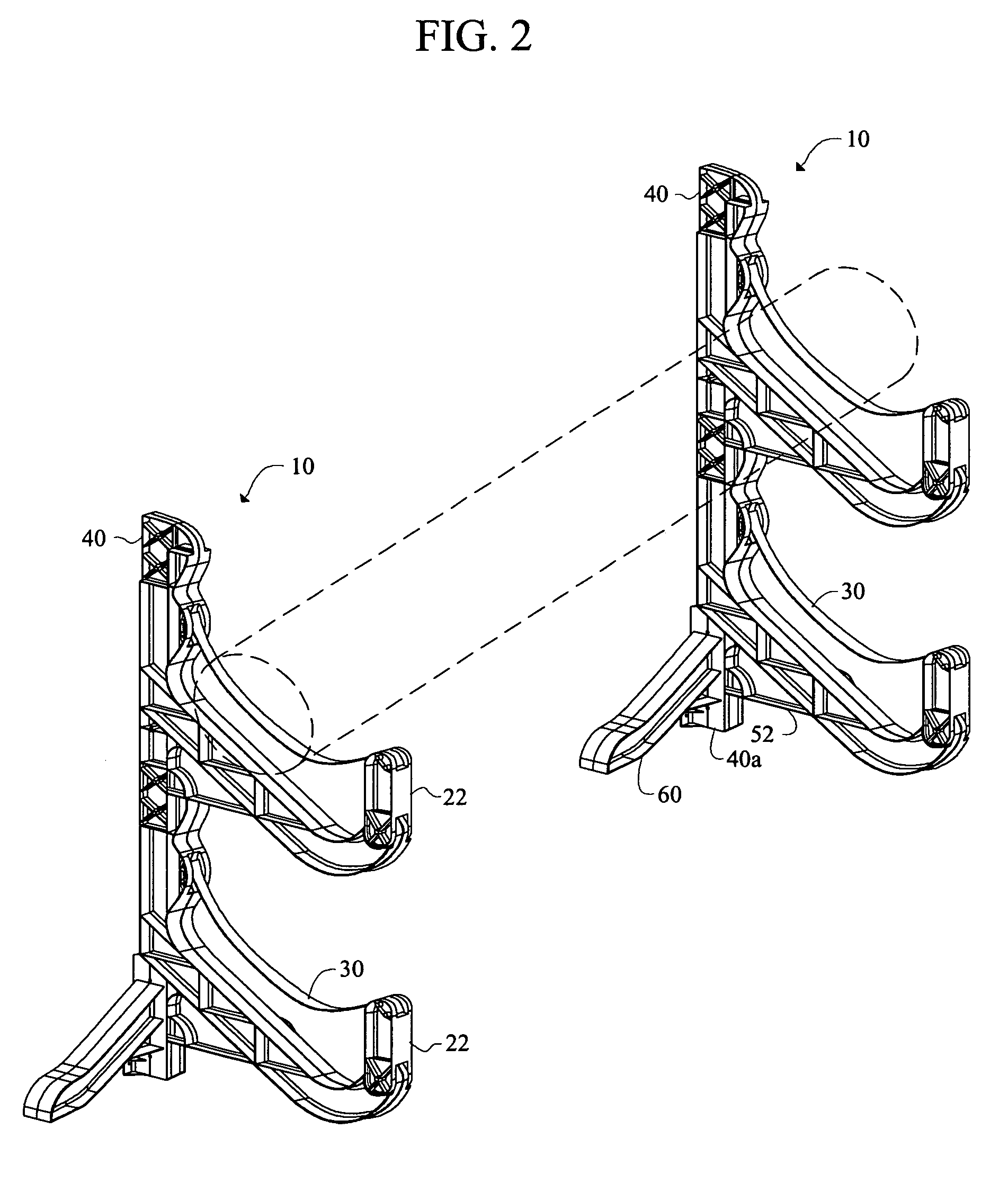
[0042]Referring now to FIG. 1, it will there be seen that a novel storage rack column is denoted as a whole by the reference numeral 10.

[0043]Two (2) of said storage rack columns 10 are placed in side-by-side relation to one another to form a simple storage rack, as depicted in FIGS. 1 and 2. Any number of such storage rack columns 10 may be employed to form larger storage racks. They may also be secured to one another in a back-to-back relation.

[0044]Storage rack column 10 is formed of a plurality of storage rack modules. Each storage rack module includes a support arm that extends in cantilever fashion from a vertical support column. In the example of FIG. 1, each storage rack column 10 includes two (2) storage rack modules. Upper support arm 12 is a part of the first module and lower support arm 14 is a part of the second module.

[0045]Upper support arm 12 is formed integrally with vertical support column 16 and lower support arm 14 is formed integrally with vertical support colum...


PUM


Abstract

A storage rack is formed by a plurality of stacked modules where each module includes a vertical support column and a support arm that extends outwardly and downwardly from the vertical support column at an angle of about thirty degrees. A barrier arm is pivotally mounted to a distal free end of the support arm. A strap extends from a first, inner end of the support arm to the barrier arm. Elongate objects placed atop the strap cause the barrier arm to pivot into a vertical position to create a barrier that prevents objects from rolling or sliding in a direction away from the vertical support column. When the elongate object is lifted from the support arm, the tension in the strap is released and the barrier arm pivots into a horizontal position of repose to facilitate removal of the object from the support arms.

Description

CROSS REFERENCE TO RELATED APPLICATION[0001]This disclosure claims benefit of a pending provisional application filed by the same inventor on Aug. 14, 2003, bearing Ser. No. 60 / 481,229.BACKGROUND OF THE INVENTION[0002]This invention relates to storage racks for large, elongated objects such as recreational kayaks, canoes, sailboards, surfboards, cargo boxes, and the like. The novel storage rack may also hold pipes, missiles, and other substantially straight items.[0003]One shortcoming of prior art racks or shelves is that they are difficult to load and unload. The item to be stored must be lifted to the height of the shelf upon which it is to be stored, or even higher if the rack includes an upwardly-extending barrier designed to prevent the stored item from rolling or sliding off the shelf.[0004]Thus there is a need for a storage rack that is easier to load and unload than the storage racks of the prior art.[0005]Many of the known storage racks are also of complex construction and ...

Claims


Application Information

Patent Timeline
IPC IPC(8): A47F7/00A47F1/14
CPCA47B81/00
Inventor ALDERMAN, THOMAS E.
Owner SUSPENZ
Why Eureka
Try Eureka