Brushless motor

a brushless motor and inner rotor technology, applied in the direction of dynamo-electric machines, electrical appliances, magnetic circuits, etc., can solve the problem of providing a low output torque per current, and achieve the effect of increasing output torque and increasing iron loss

Active Publication Date: 2007-04-10
MITSUBISHI ELECTRIC CORP
View PDF23 Cites 8 Cited by
  • Summary
  • Abstract
  • Description
  • Claims
  • Application Information

AI Technical Summary

Benefits of technology

[0006]The present invention is intended to obviate the problem as referred to above, and has for its object to provide a brushless motor which is capable of increasing output torque while suppressing an increase in iron loss.
[0008]With the brushless motor according to the present invention, the output torque thereof can be increased while suppressing an increase in iron loss.

Problems solved by technology

Such a conventional brushless motor having the magnets of radial orientation involves the following problem; that is, the density of magnetic flux in a gap between the stator and the rotor is low, and the value of an induced voltage becomes accordingly low, thus providing a low output torque per current.

Method used


Image

  • Brushless motor
  • Brushless motor
  • Brushless motor

Examples


embodiment 1

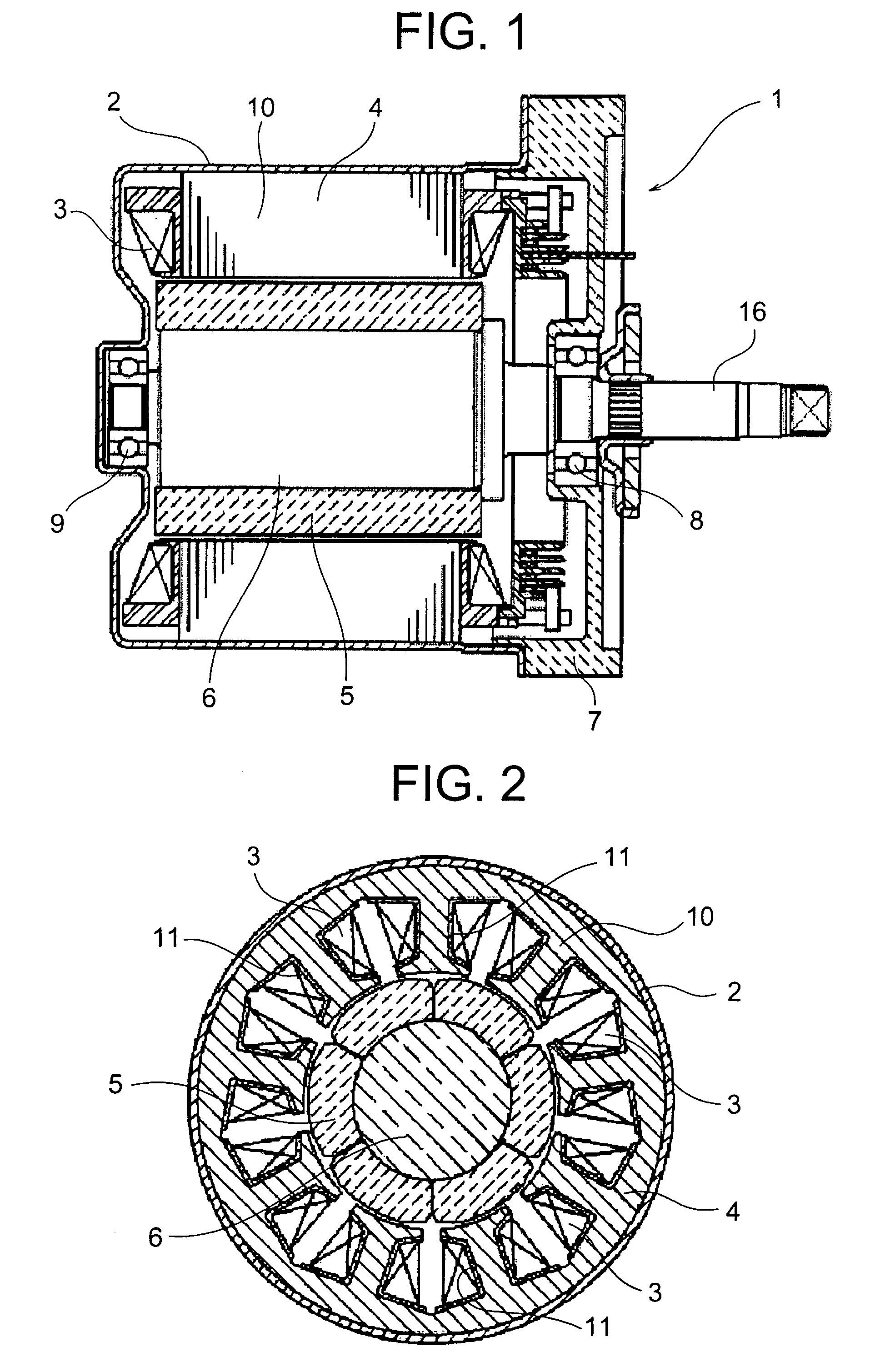
[0026]FIG. 1 is a cross sectional side view when a brushless motor according to the first embodiment of the present invention is cut along an axial direction. FIG. 2 is a cross sectional front view when the brushless motor of FIG. 1 is cut along a diametral direction.

[0027]This brushless motor, generally designated at reference numeral 1, is comprised of a motor for an electrohydraulic power steering apparatus which is constantly driven to operate even during non-steering operation, and which is provided with a rotor 6 fixedly mounted on a shaft 16, and a stator 4 that is press-fitted into and firmly attached to a frame 2 of a bottomed cylindrical shape formed of steel sheet, and is arranged around the outer periphery of the rotor 6 with a gap formed therebetween.

[0028]The rotor 6 is rotatably supported on a housing 7 made of aluminum and the frame 2 through the shaft 16 at its opposite ends by means of a first bearing 8 attached to the housing 7 and a second bearing 9 attached to t...

embodiment 2

[0052]FIG. 14 is a front elevational view that illustrates a magnet 5 according to a second embodiment of the present invention, and FIG. 15 is a cross sectional view when the magnet 5 of FIG. 14 is cut along an axial direction.

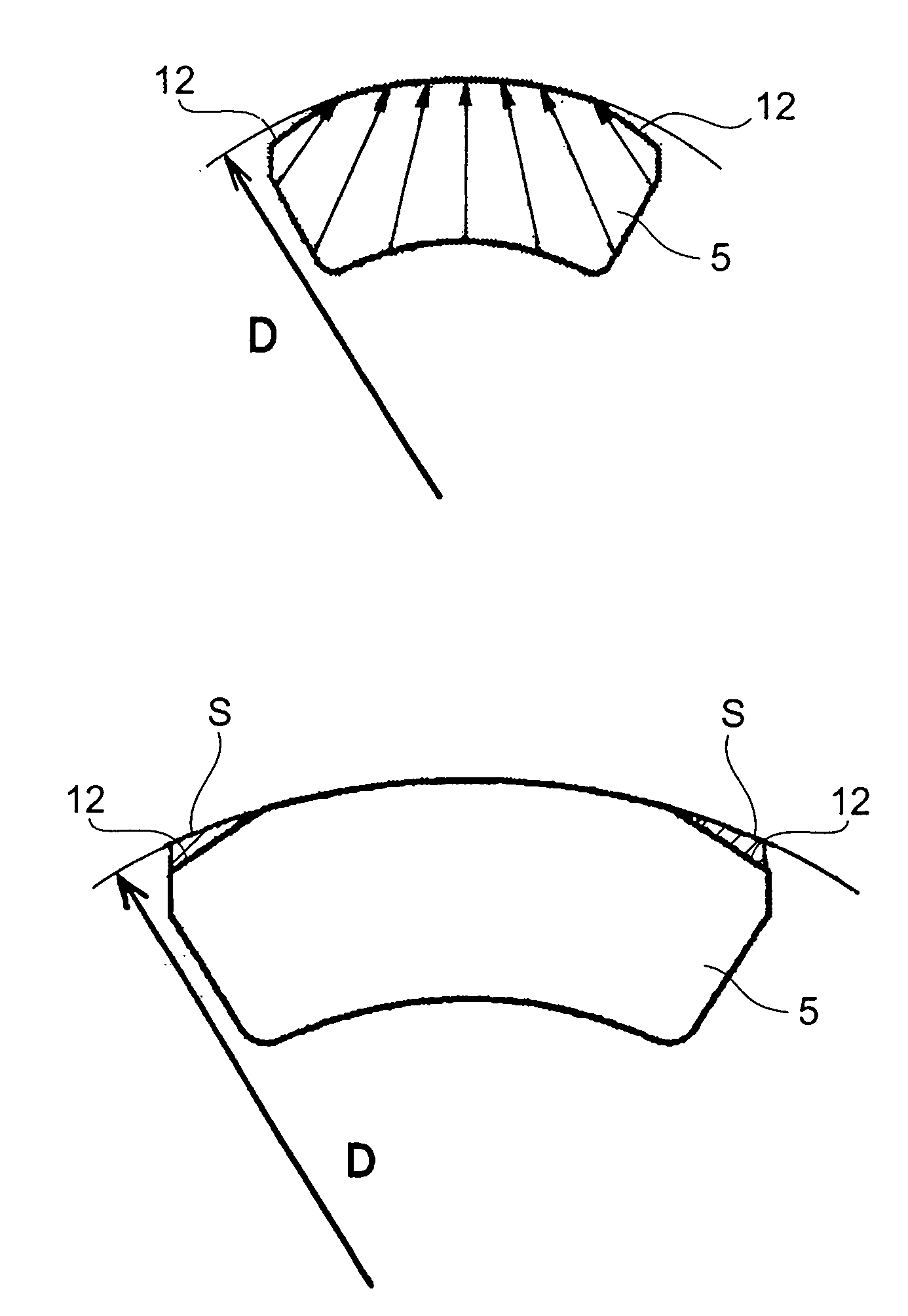
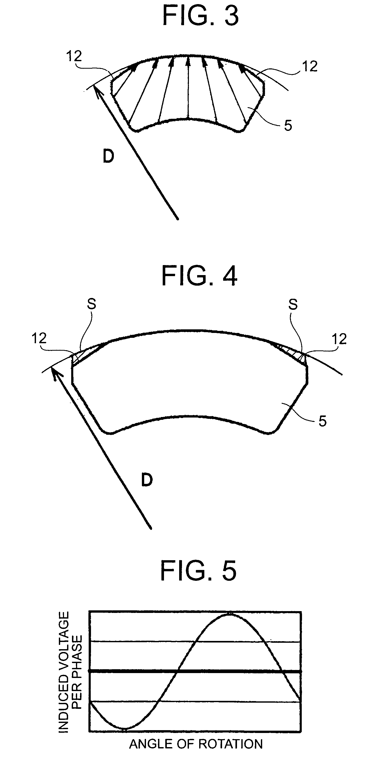
[0053]Similar to the above-mentioned first embodiment, this magnet 5 is magnetized in reverse radial orientation in such a manner that a magnetic field directed toward the stator 4 converges toward the stator 4, and the magnet 5 has a pair of notched portions 12 formed at opposite ends of the outer peripheral surface thereof. In addition, the magnet 5 is magnetized so that the magnetic field directed toward the stator 4 converges on an axially central side of the core 10 on a cross section taken along the axial direction (center orientation), as shown in FIG. 15.

[0054]In the brushless motor of this second embodiment, the same advantages as those of the first embodiment can be obtained, and besides, the magnetic field of the magnet 5 is arranged in center orie...


PUM


Abstract

A brushless motor is capable of increasing output torque while suppressing an increase in iron loss. A plurality of magnets are magnetized in reverse radial orientation in such a manner that magnetic fields directed toward a stator converge toward the stator, and each of the magnets is provided at opposite ends of its outer peripheral surface with a pair of notched portions that are cut away to gradually approach in an axial direction as they proceed from an intermediate portion to the opposite ends.

Description

BACKGROUND OF THE INVENTION[0001]1. Field of the Invention[0002]The present invention relates to an inner rotor type brushless motor that is provided with a rotor having a plurality of segment type magnets disposed inside a stator so as to face the stator.[0003]2. Description of the Related Art[0004]As a conventional inner rotor type brushless motor, there has hitherto been known one that is provided with a rotor having segment type magnets of radial orientation (i.e., a magnetic field being directed toward the stator and diffusing toward the stator) (for example, see a patent document: Japanese PatentApplication Laid-Open No. 2003-230239)[0005]Such a conventional brushless motor having the magnets of radial orientation involves the following problem; that is, the density of magnetic flux in a gap between the stator and the rotor is low, and the value of an induced voltage becomes accordingly low, thus providing a low output torque per current.SUMMARY OF THE INVENTION[0006]The prese...

Claims


Application Information

Patent Timeline
Patent Type & Authority Patents(United States)
IPC IPC(8): H02K21/12
CPCH02K1/278
Inventor OHATA, KATSUMINAKANO, MASATSUGUTAKAKI, TETSUNAO
Owner MITSUBISHI ELECTRIC CORP
Why Eureka
Try Eureka