Core material, stator core, and motor provided with stator core

a stator core and core material technology, applied in the direction of dynamo-electric machines, electrical equipment, magnetic circuit shapes/forms/construction, etc., can solve the problems of increasing iron loss, affecting the efficiency of motors, and reducing so as to suppress the increase in iron loss, maintain the circularity of teeth, and suppress the effect of compressive stress at the joint surfaces

Active Publication Date: 2013-11-07
PANASONIC INTELLECTUAL PROPERTY MANAGEMENT CO LTD
View PDF2 Cites 1 Cited by
  • Summary
  • Abstract
  • Description
  • Claims
  • Application Information

AI Technical Summary

Benefits of technology

[0012]In this manner, when the core material according to the present invention is plastically deformed, the joint surfaces can be joined to each other substantially in parallel to each other without any mismatch between the joint surfaces. Therefore, the core material according to the present invention can

Problems solved by technology

In this manner, with the conventional configuration, an inconstant joint state at each of the connecting portions raises the problem of degradation of circularity of a tooth.
In view of this, a machining force for forming a core mate

Method used


Image

  • Core material, stator core, and motor provided with stator core
  • Core material, stator core, and motor provided with stator core
  • Core material, stator core, and motor provided with stator core

Examples


first exemplary embodiment

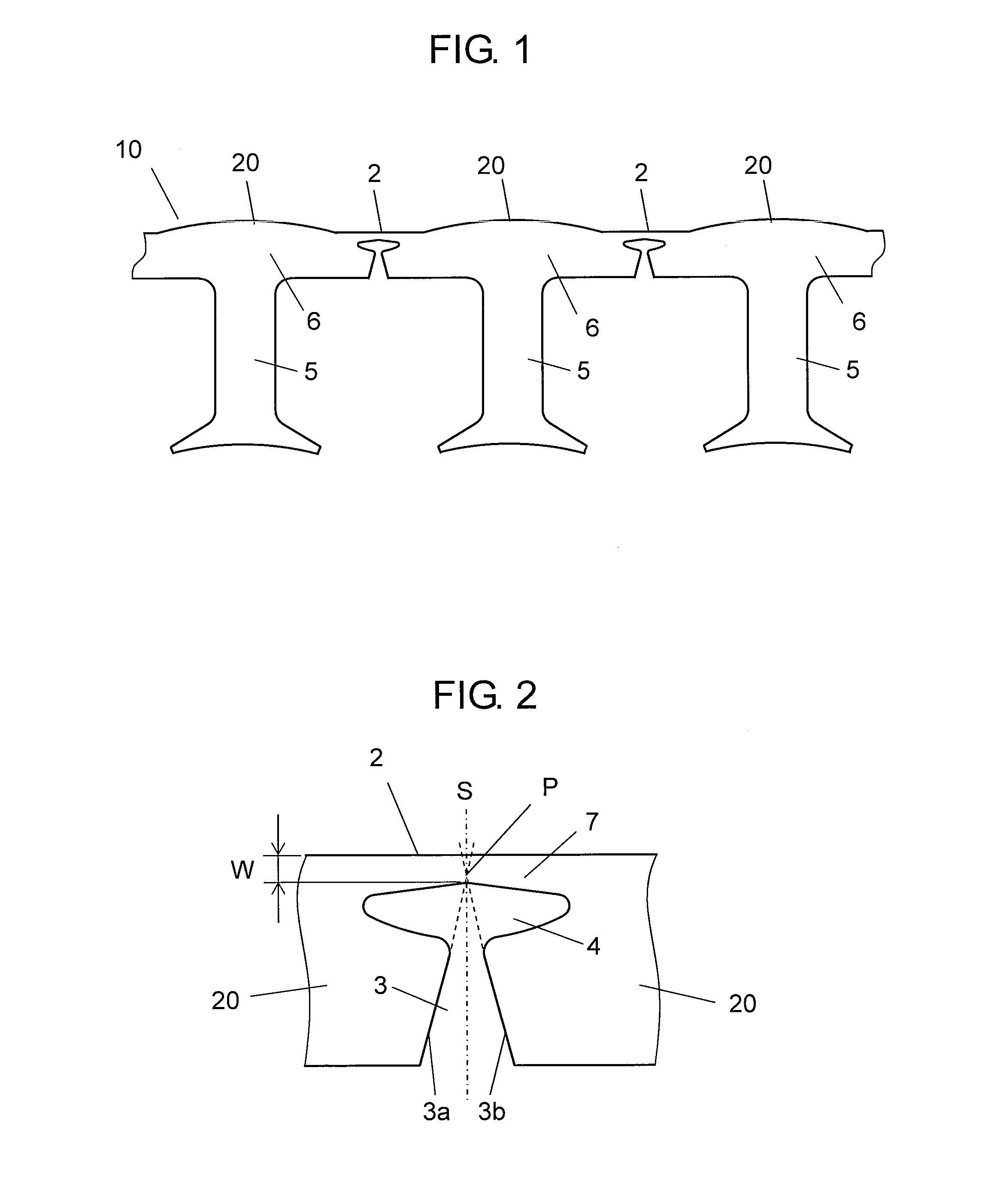
[0030]FIG. 1 is a plan view showing core material 10 in a first exemplary embodiment according to the present invention.

[0031]As shown in FIG. 1, core material 10 is constituted of a plurality of core pieces 20 that are connected to each other via connecting portion 2. Each of core pieces 20 is constituted of tooth portion 5 and yoke portion 6. Core material 10 is formed by punching a belt-like magnetic steel sheet into a predetermined shape.

[0032]In this manner, core material 10 in the present exemplary embodiment includes the plurality of core pieces 20, each having tooth portion 5 and yoke portion 6, connected to each other via connecting portions 2. And then, each of connecting portions 2 in core material 10 is plastically deformed, thereby forming an annular stator core.

[0033]FIG. 2 is a plan view showing the vicinity of connecting portion 2 of core material 10 in the first exemplary embodiment according to the present invention.

[0034]As shown in FIG. 2, connecting portion 2 is...

second exemplary embodiment

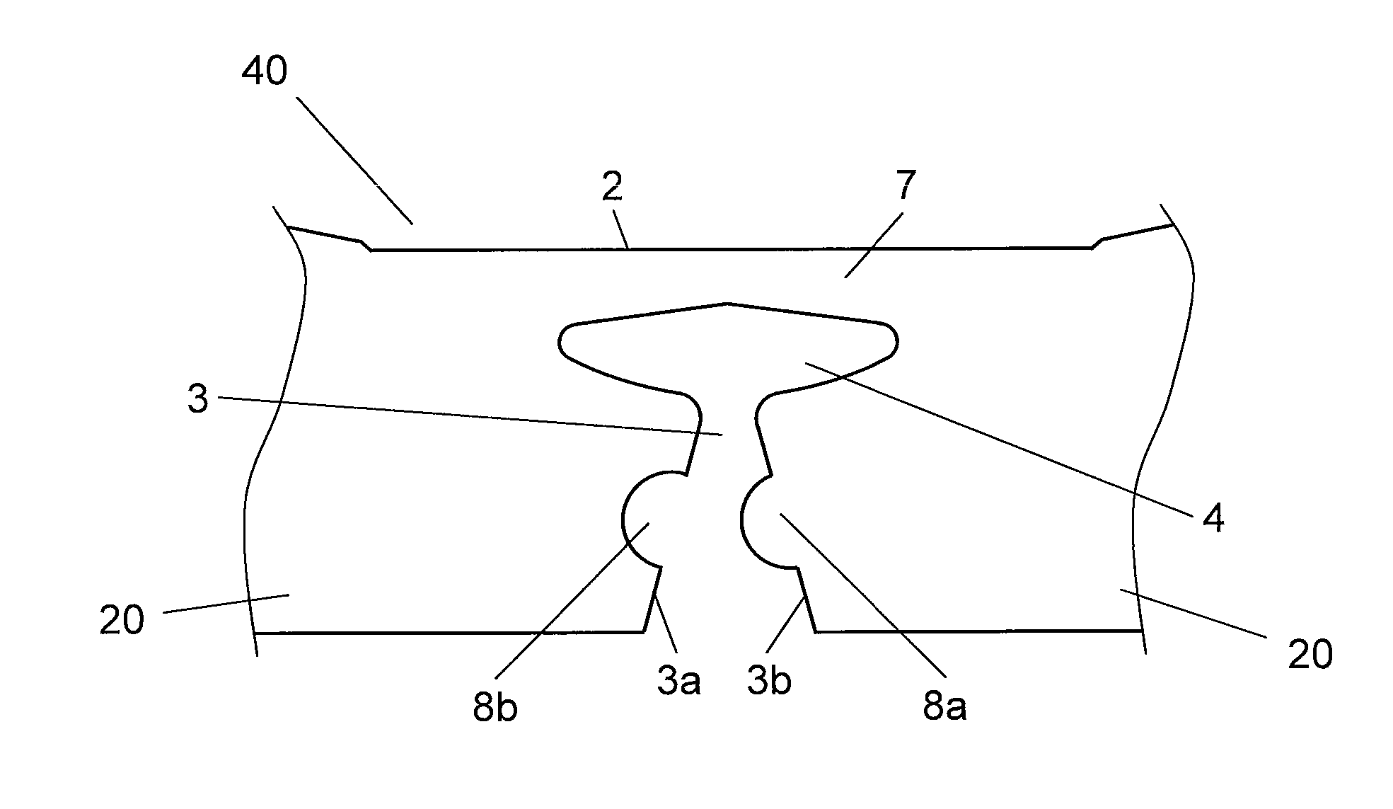
[0050]FIG. 7 is a plan view showing the vicinity of a connecting portion of core material 40 in a second exemplary embodiment according to the present invention.

[0051]In FIG. 7, the same constituent elements as those in the first exemplary embodiment shown in FIG. 1 are designated by the same reference numerals, and therefore, their detailed description will be omitted. Core material 40 further includes convex 8a formed on one of joint surfaces 3a and 3b of notch portion 3 and concave 8b formed in the opposite joint surface so as to conform with convex 8a in the present exemplary embodiment in addition to the configuration in the first exemplary embodiment.

[0052]A description will be given below in detail of core material 40 such constituted as described above.

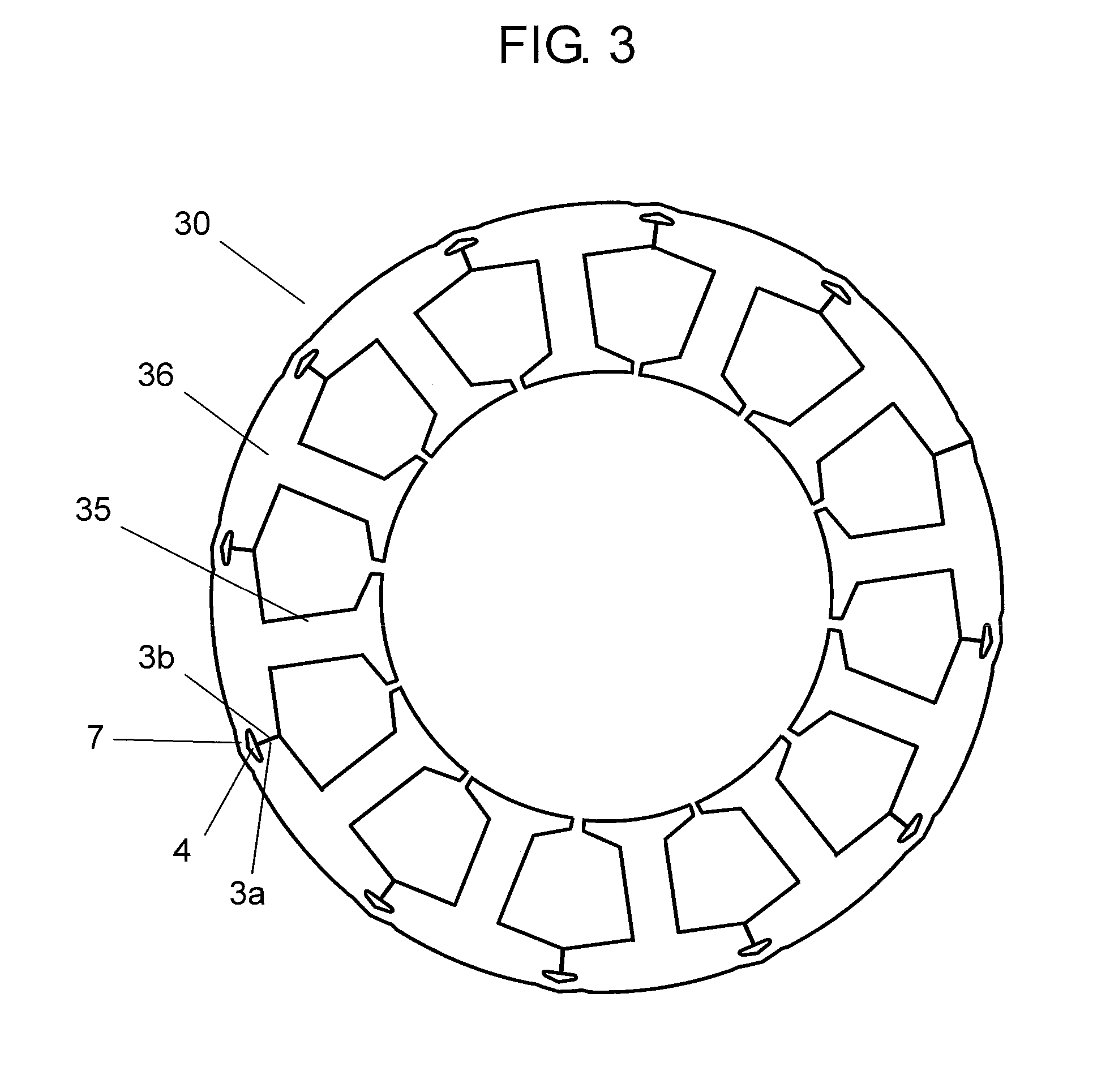
[0053]First, in forming a stator core, convex 8a and concave 8b are conformed to each other during plastic deformation. And then, all connecting portions 2 are plastically deformed, and thus, the stator core shown in FIG. 3 is...

third exemplary embodiment

[0057]FIG. 9 is a cross-sectional view showing motor 50 in a third exemplary embodiment according to the present invention.

[0058]As shown in FIG. 9, motor 50 in the present exemplary embodiment includes rotor 60 and stator 70. Rotor 60 is rotated about rotary shaft 64 while holding magnet 63 around columnar rotor yoke 61. In stator 70, winding coil 71 is wound around stator core 30.

[0059]In rotor 60, rotary shaft 64 is inserted through rotor yoke 61, and further, rotary shaft 64 is securely fixed to rotor yoke 61. Ring-like magnetized magnet 63 is integrally secured around rotor yoke 61. Rotary shaft 64 extending through rotor yoke 61 is inserted through bearings 65, and thus, rotor 60 is rotatably supported by bearings 65.

[0060]Moreover, stator 70 is provided with stator cores 30 that have been described in the first or second exemplary embodiment. The present exemplary embodiment exemplifies that a plurality of pieces of stator cores 30 obtained by plastically deforming core mater...


PUM


Abstract

In a core material according to the present invention, a predetermined number of core pieces, each having a tooth portion and a yoke portion, are connected to each other via connecting portions. Each of the connecting portions includes: a V-shaped notch portion; a through hole that is formed at a tapered portion of the notch portion with a diameter elongated in a connection direction; and a thin portion that is formed outside of the through hole and connects the core pieces to each other. The width of the thin portion is more increased apart from the axis of symmetry of two sides constituting the V shape of the notch portion, and further, an intersection between extension lines of the two sides constituting the V shape lies within 0.3 W from the inner side of the thin portion in a notch direction and within the thin portion when W designates the width of the thin portion along the axis of symmetry.

Description

TECHNICAL FIELD[0001]The present invention relates to a core material for a stator core to be used in a motor such as a brushless motor.BACKGROUND ART[0002]There has been conventionally known a technique for deforming a core material so as to form a stator core for a motor. In other words, in fabricating this kind of stator core, the yield of a magnetic steel sheet during fabrication is increased by the following technique. First, when a core material is punched from a magnetic steel sheet, not an annular core material but a belt-like core material is punched. At this time, the core material is constituted of a plurality of core pieces continuous to each other in a belt-like manner. The punched core material is deformed into an annular shape, so that a stator core is obtained.[0003]Specifically, a predetermined number of core pieces, each having a tooth portion and a yoke portion, are punched from the magnetic steel sheet in the state in which they are connected to each other via a ...

Claims


Application Information

Patent Timeline
IPC IPC(8): H02K1/12
CPCH02K1/12H02K1/148
Inventor OKADA, YUKIHIROCHAMURA, MINORUECHIZEN, YASUJINAKAMARU, TOORULI, HU
Owner PANASONIC INTELLECTUAL PROPERTY MANAGEMENT CO LTD
Why Eureka
Try Eureka