Treadmill roller structure and treadmill

a technology of roller structure and treadmill, which is applied in the direction of conveyor parts, roller-ways, gymnastic exercises, etc., can solve the problems of inability to find appropriate locations for sport activities and fitness exercises, large area taken by the treadmill, and partial losses during the transfer of motor output power, etc., to achieve the effect of reducing friction losses during power transfer, improving motor performance, and saving spa

Inactive Publication Date: 2010-12-30
YIHSUAN ENTERPRISE
View PDF22 Cites 26 Cited by
  • Summary
  • Abstract
  • Description
  • Claims
  • Application Information

AI Technical Summary

Benefits of technology

[0008]The objective of the instant disclosure is to provide a treadmill roller structure and a treadmill which configures the motor and the gear set inside or outside of the roller, such that the roller can actively rotate, facilitating enhancement in performance of the motor and the feature of space saving. In addition, it is not required to use a belt to bring the roller to rotate, so the friction losses during power transfer can be desirably reduced, thereby increasing efficiency of the motor as well.

Problems solved by technology

In the modern world, dense metropolitan population and crowded living environment make it difficult for the city residents to find appropriate locations for sport activities and fitness exercises.
However, separate installations of the motor and the front roller in a prior art treadmill may cause following drawbacks.
It is required to reserve space in advance for placement of the motor in the treadmill base, so the area taken by the treadmill can be exceedingly large which may not be suitable for domestic applications.
Frictions exist respectively between the belt and motor output axle as well as between the belt and the front roller, and such frictions neutralize certain parts of motor output power, undesirably leading to partial losses during transfer of motor output power.
Furthermore, idle rotations tend to occur in case that the speed of belt transfer becomes too fast while the contact friction between the belt and the front roller is insufficient, so the power output from the motor may not be efficiently transferred the front roller, thus also resulting in unwanted partial losses in motor output power during power transfer.

Method used


Image

  • Treadmill roller structure and treadmill
  • Treadmill roller structure and treadmill
  • Treadmill roller structure and treadmill

Examples


Embodiment Construction

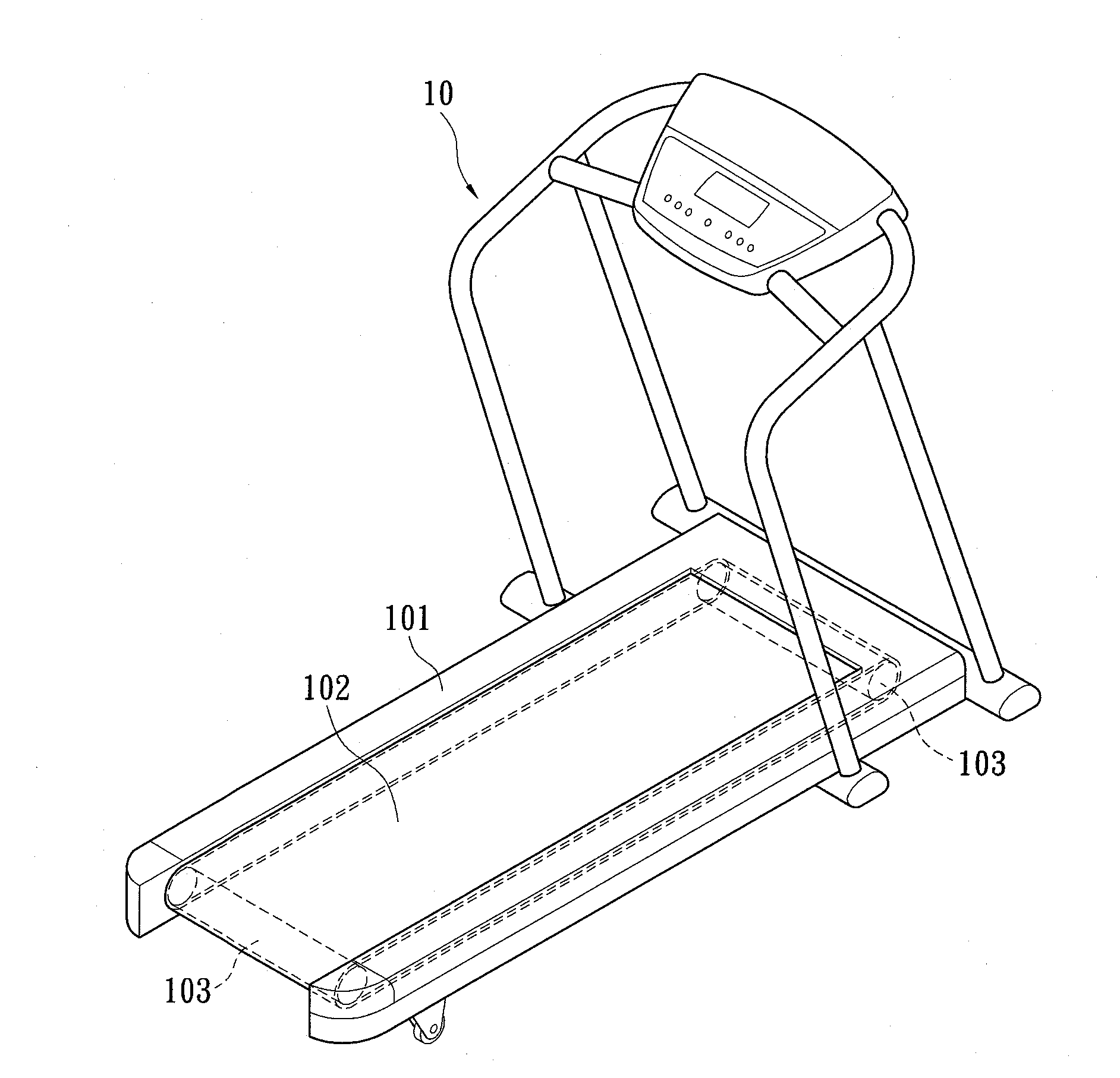
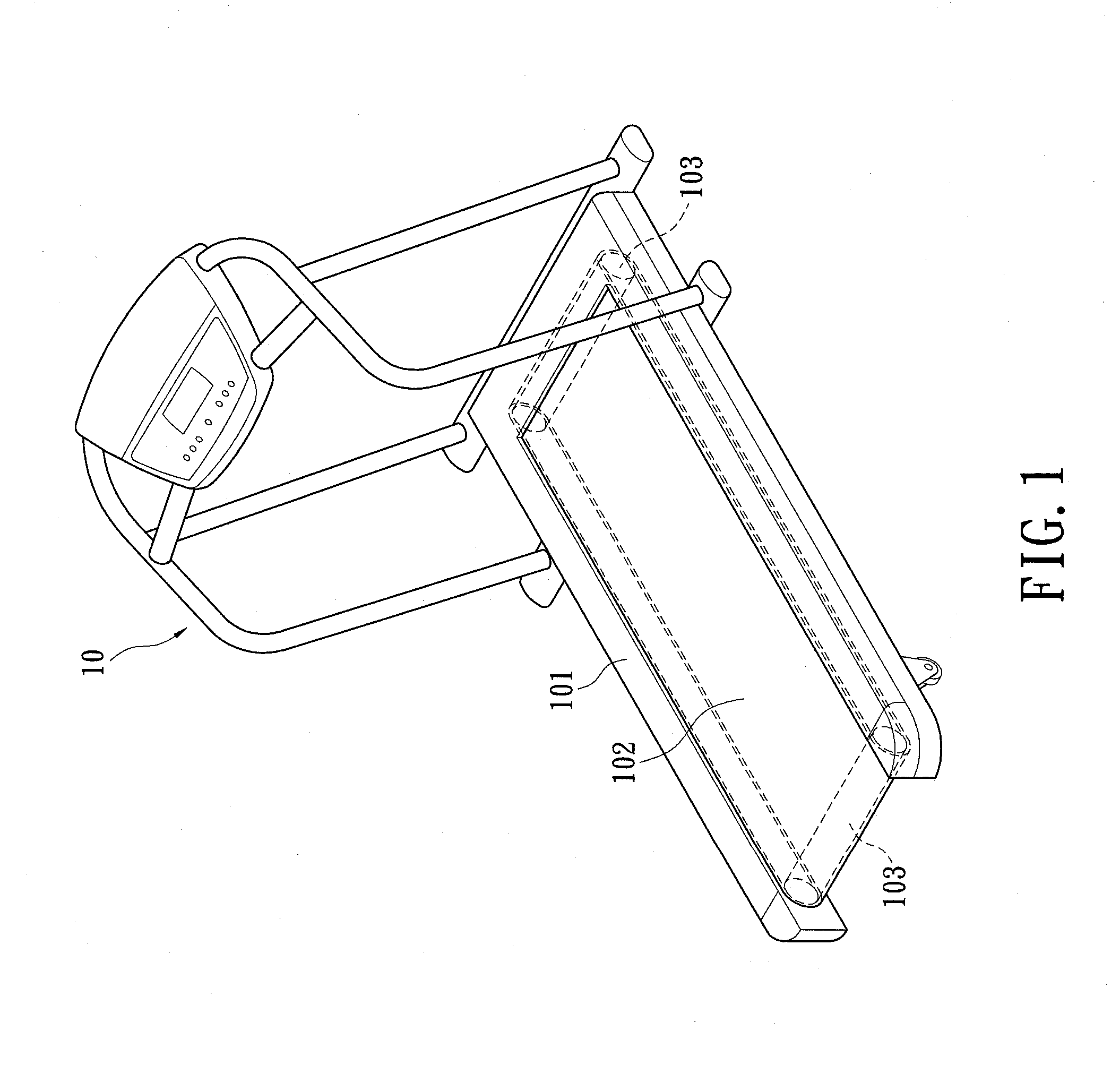
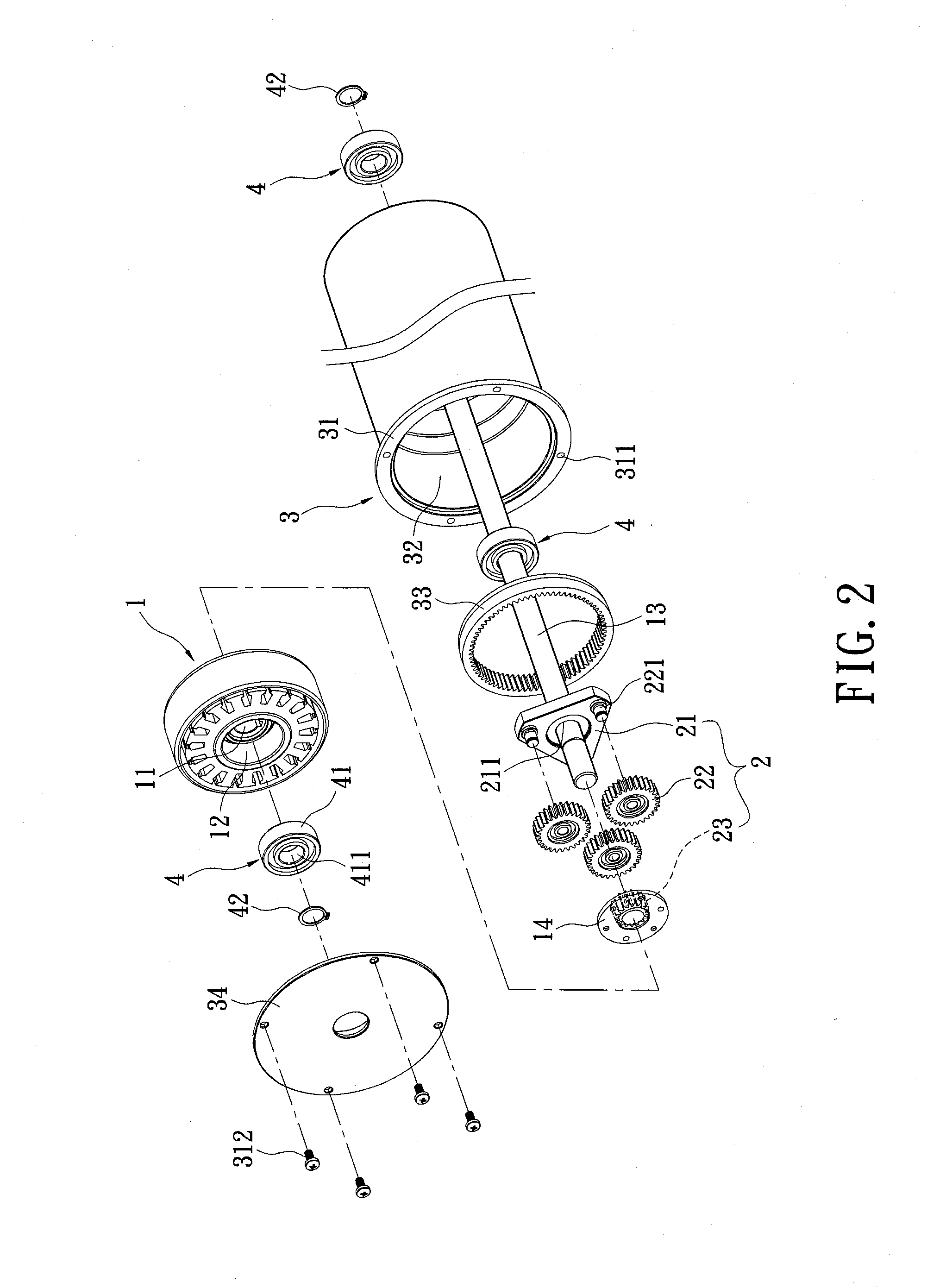
[0025]Referring initially to FIGS. 1, 2 and 3. The instant disclosure provides a treadmill roller structure. The roller structure is installed at the front and the rear end of the base 101 of a treadmill 10 to the treadmill belt 102 around the front and the rear roller 103. The roller 103 comprises a motor 1, a gear set 2, a case 3 and a plurality of motion limiting assemblies 4.

[0026]The motor 1 is an out-runner motor having a motor axle bore 11, an accommodation chamber 12, a spindle 13 and a power output section 14. The motor axle bore 11 is located in the accommodation chamber 12 of the motor 1. The accommodation chamber 12 is able to accommodate the motion limiting assemblies 4. The spindle 13 passes through the motor axle bore 11 of the motor 1, the gear set 2, the case 3, and the motion limiting assemblies 4. The spindle 13 is a fixed supporting structure that does not rotate; rather, the motor 1 is installed through the spindle 13 in a fashion that the rotating belt of the m...


PUM


Abstract

A treadmill roller structure comprises a motor, a gear set and a case. The motor is an out-runner motor. The power output section of the motor rotates about stationary spindle. The rotary power output section is engaged to the gear set, while the gear set is in turn engaged to the case, thus allowing the case to rotate relatively to the spindle of the motor as well. The roller structure does not require a driving belt to transfer power from the motor to the roller, thus reduces the power loss due to frictional force during power transfer through belt driving, which enhances the performance of the motor and offers a space-saving feature. In addition, the instant disclosure also provides a treadmill.

Description

BACKGROUND OF THE INVENTION[0001]1. Field of the Invention[0002]The instant disclosure relates to a treadmill roller structure; in particular, the instant disclosure relates to a roller structure in a treadmill device.[0003]2. Description of Related Art[0004]In the modern world, dense metropolitan population and crowded living environment make it difficult for the city residents to find appropriate locations for sport activities and fitness exercises. To address such an issue, indoor sport equipments, such as treadmills, exercise bikes or skiing machines are developed. These equipments can be installed indoor, thus breaking the spatial constrains and temporal limitations.[0005]In a conventional treadmill, a drive belt is employed to drive the rollers. In a conventional setup, a front roller and a rear roller are respectively installed at the front side and the rear side of the base, and a treadmill belt is then set between the front roller and the rear roller, thereby enabling the t...

Claims


Application Information

Patent Timeline
Patent Type & Authority Applications(United States)
IPC IPC(8): A63B22/02
CPCB65G39/09A63B22/0235
Inventor HUANG, TE-LI
Owner YIHSUAN ENTERPRISE
Why Eureka
Try Eureka