

Fluid Dynamic Bearing Apparatus and a Motor Using the Same
- Summary
- Abstract
- Description
- Claims
- Application Information
AI Technical Summary
Benefits of technology
Problems solved by technology
Method used
Image

Examples
first embodiment
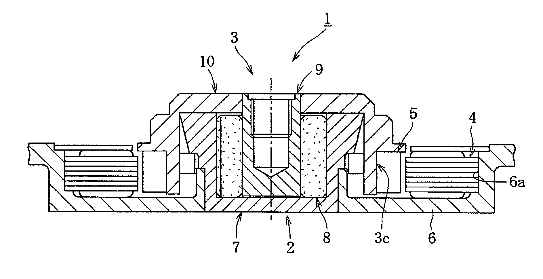
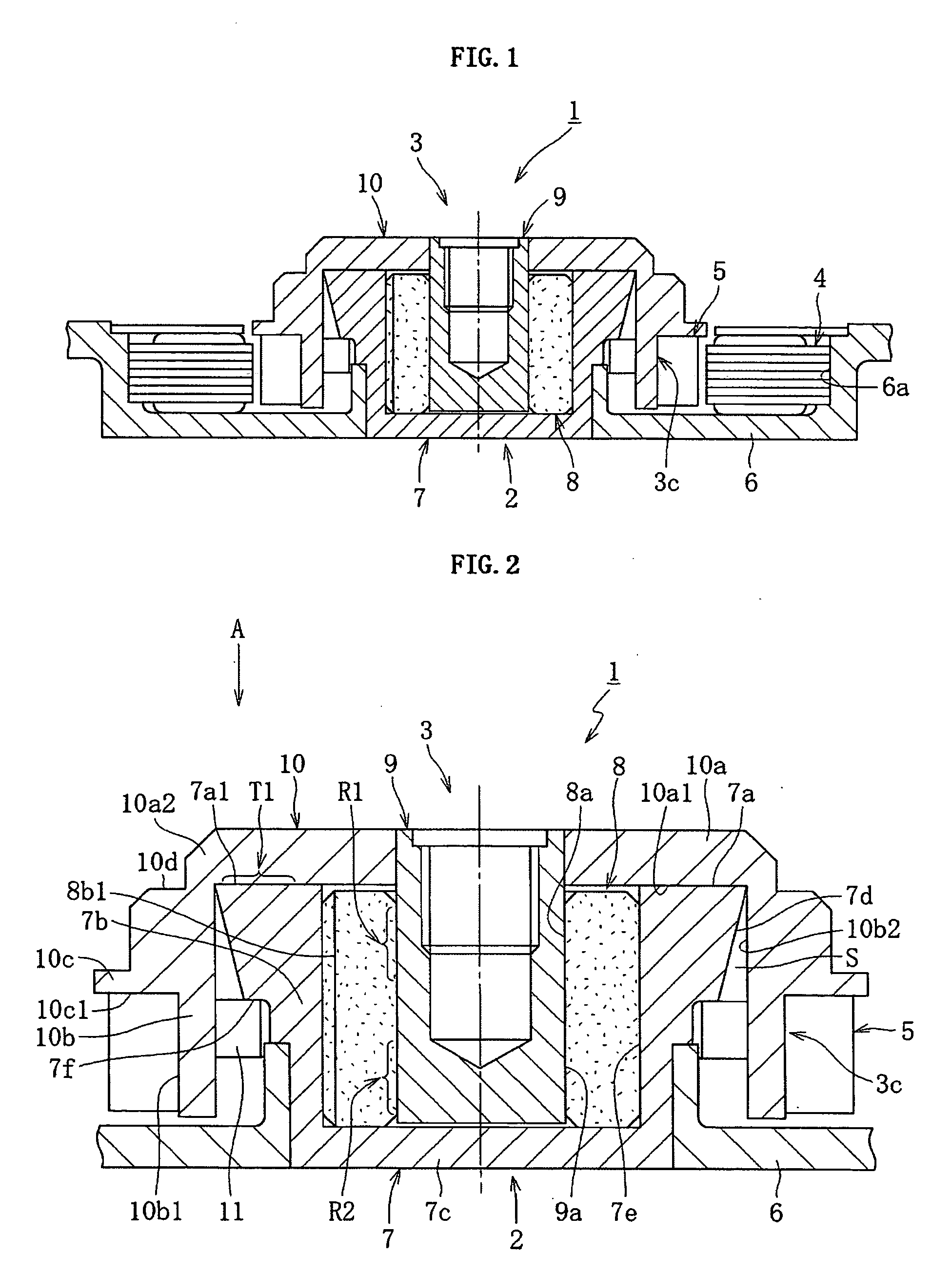
[0033]FIG. 1 shows a constitutional example of a spindle motor for information appliances incorporating a fluid dynamic bearing apparatus 1 according to the present invention. This spindle motor for information appliances is for use in disk drive units such as HDD, and comprises a fluid dynamic bearing apparatus 1 having a fixed-side member 2 and having a rotational-side member 3 which is freely rotatable relative to the fixed-side member 2 and, for example, a stator coil 4 and a rotor magnet 5 which oppose each other across a gap in the radial direction, and a bracket 6. The stator coil 4 is attached on the inner side face 6a of the bracket 6, and the rotor magnet 5 is attached on the outer periphery of the rotational-side member 3, more specifically on the outer periphery of a disk hub 10 which can retain one or a plurality of disk-shaped information recording media such as magnetic disks on its outer periphery. The housing 7 of the fluid dynamic bearing apparatus 1 is attached on...
second embodiment
[0053]FIG. 7 conceptionally and partially shows a constitutional example of a fluid dynamic bearing apparatus 21 according to the present invention and of a spindle motor for information appliances integrating this fluid dynamic bearing apparatus 21. This spindle motor for information appliances is for use in disk drive units such as HDD, and comprises a fluid dynamic bearing apparatus 21 which freely rotatably supports a shaft member 29 by a fixed-side member 2, a stator coil 4 and a rotor magnet 5 which, for example, oppose each other across a gap in the radial direction (refer to FIG. 1) and a bracket 6. The rotor magnet 5 is attached on the outer periphery of a disk hub 30 as a member having a portion 3c for mounting the rotor magnet 5. This disk hub 30 retains one or a plurality of magnetic disks and like disk-shaped information recording media on its outer periphery. The housing 7 of the fluid dynamic bearing apparatus 21 is attached on the inner periphery of the bracket 6. Wh...
third embodiment
[0068] As mentioned above, also in the third embodiment, the disk hub 30 is molded integrally with the shaft member 29 by insert molding, whereby the process of mounting of the disk hub 30 to the shaft member 29 can be dispensed with and the cost of assembling the motor can be reduced. Furthermore, high mounting precision between the disk hub 30 and shaft member 29 can be obtained so that sufficient fixing force between them can be ensured. Moreover, a magnetic shielding member is disposed in a position in the disk hub 40 which opposes the rotor magnet, whereby magnetic flux leakage from the rotor magnet can be suppressed. Furthermore, the disk hub 40 can be insert-molded with the core as in the variation example shown in FIG. 5 also in this embodiment, and accordingly the molding dimensional accuracy of the disk hub 40 can be increased.
[0069]FIG. 9 is an enlarged sectional view of a polygon scanner motor integrating a fluid dynamic bearing apparatus 41 according to a fourth embodim...
PUM
| Property | Measurement | Unit |
|---|---|---|
| Magnetism | aaaaa | aaaaa |
| Hydrodynamic wave | aaaaa | aaaaa |
Abstract
Description
Claims
Application Information