Magnetically actuated reciprocating motor and process using reverse magnetic switching

a reciprocating motor and magnetic switching technology, applied in the field of reciprocating motors, can solve the problems of non-movement of solenoid and significant loss of efficiency

Inactive Publication Date: 2013-01-01
GOSVENER KENDALL C
View PDF30 Cites 15 Cited by
  • Summary
  • Abstract
  • Description
  • Claims
  • Application Information

AI Technical Summary

Benefits of technology

[0014]The magnetically actuated reciprocating motor of the present invention solves the problems and provides the benefits identified above. That is to say, the present invention discloses a new and improved reciprocating motor comprising a fixed elongated magnetic actuator having an axially charged permanent magnet at each end of a shaft and a solenoid assembly having a solenoid made up of a wire coil that is wrapped around a nonferrous spool having an open center to provide an axially charged magnetic field. The fixed shaft of the magnetic actuator is received in the open center of the spool in a manner that allows the solenoid assembly to reciprocate relative to the magnetic actuator. The magnetic polarities of the ends of the solenoid are rapidly switched such that one end of the solenoid, and therefore the solenoid assembly, is being attracted to the magnet at one end of the shaft while the other end of the solenoid is being repelled by the magnet at the opposite end of the shaft. As a result, the solenoid alternates between being magnetically attracted to or repelled by each permanent magnet to reciprocate the solenoid assembly up and down the shaft and drive an output shaft that is operatively connected to the moving solenoid assembly. As with the '928 Application, the magnetically actuated reciprocating motor of the present invention does not utilize an electromagnet. This arrangement eliminates the problems associated with the permanent magnets being attracted to the iron core of an electromagnet, which can result in significant loss of efficiency and non-movement of the solenoid. The magnetically actuated reciprocating motor of the present invention does not rely on an external source of power, such as a prime mover or the like, to pivot, rotate or otherwise move the permanent magnets from an attracting position to a repelling position in order to reciprocally drive the magnetic actuator. The new reciprocating motor is relatively simple to operate, requires a limited number of moving components and is believed to be relatively inexpensive to manufacture. The magnetically actuated reciprocating motor of the present invention drives a crankshaft so as to produce rotary power that is adaptable to a wide variety of reciprocating motor uses, including electrical power generation and vehicle motion.
[0017]In a preferred embodiment, the shaft has a tubular chamber, the first permanent magnet has a first extension member with an inward end extending into the tubular chamber from the first end of the shaft and the second permanent magnet has a second extension member with an inward end extending into the tubular chamber from the second end of the shaft. The inward end of the first extension member is disposed in spaced apart relation with the inward end of the second extension member to define a gap between the two extension members in the tubular chamber of the shaft. This configuration has been found to improve the performance of the motor of the present invention.
[0019]In contrast to the '928 Application, in which the solenoid is held stationary and the magnetic actuator reciprocates relative to the solenoid, in the present invention the solenoid (as part of the solenoid assembly) reciprocates around the shaft of the stationary magnetic actuator. In one embodiment, a magnet frame is utilized at each of the permanent magnets to interconnect the magnets with the frame and fix the magnetic actuator. The present embodiment has the advantage of allowing heavier permanent magnets without the loss of energy that would be otherwise associated with reciprocating those magnets. As well known in the art, heavier weight magnets generally provide greater magnetic force, which can then be converted into increased work output by the motor of the present invention.
[0020]Accordingly, the primary objective of the present invention is to provide a magnetically actuated reciprocating motor using reverse magnetic switching that provides the advantages discussed above and overcomes the disadvantages and limitations associated with presently available magnetically powered reciprocating motors.
[0022]It is also an important object of the present invention to provide a magnetically actuated reciprocating motor that utilizes electromagnetic force to alternatively attract and repel a solenoid relative to a pair of oppositely positioned permanent magnets mounted at the ends of a shaft received through the solenoid that does not utilize an electromagnet so as to eliminate attraction between the permanent magnets and the iron core of the electromagnet.
[0024]It is also an object of the present invention to provide a magnetically actuated reciprocating motor that does not require utilization of a prime mover or the like to provide the magnetic switching necessary to magnetically reciprocate a solenoid and drive an output shaft connected thereto.

Problems solved by technology

This arrangement eliminates the problems associated with the permanent magnets being attracted to the iron core of an electromagnet, which can result in significant loss of efficiency and non-movement of the solenoid.

Method used


Image

  • Magnetically actuated reciprocating motor and process using reverse magnetic switching
  • Magnetically actuated reciprocating motor and process using reverse magnetic switching
  • Magnetically actuated reciprocating motor and process using reverse magnetic switching

Examples


Embodiment Construction

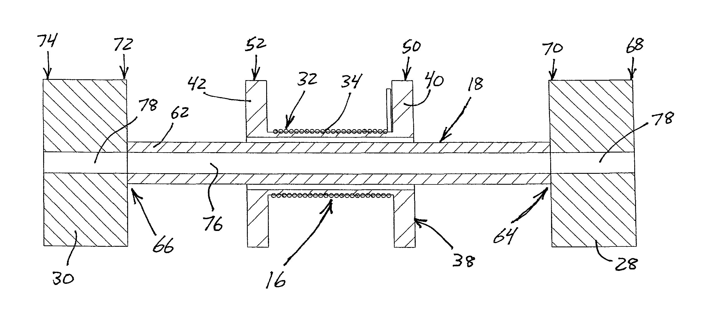
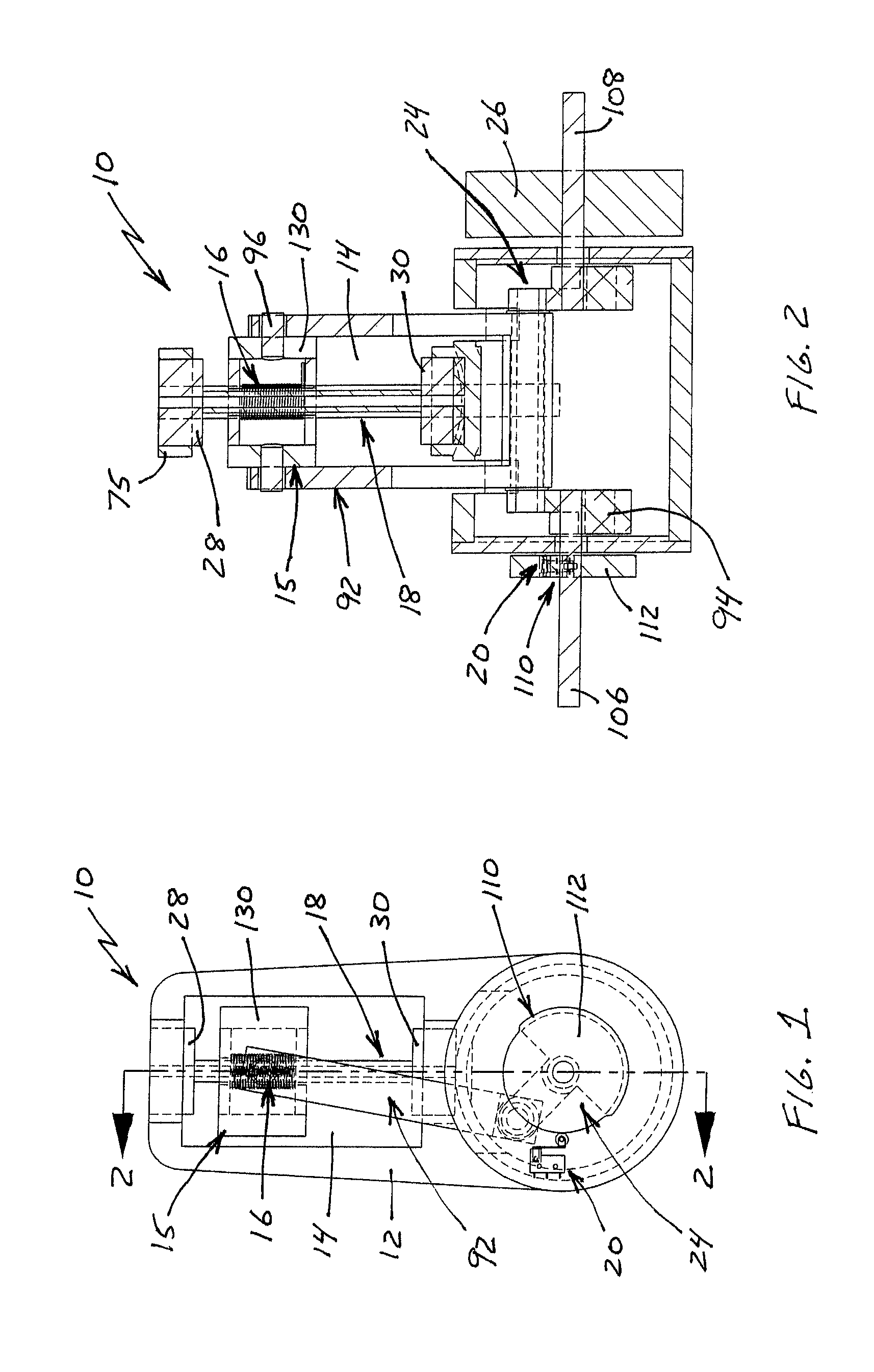
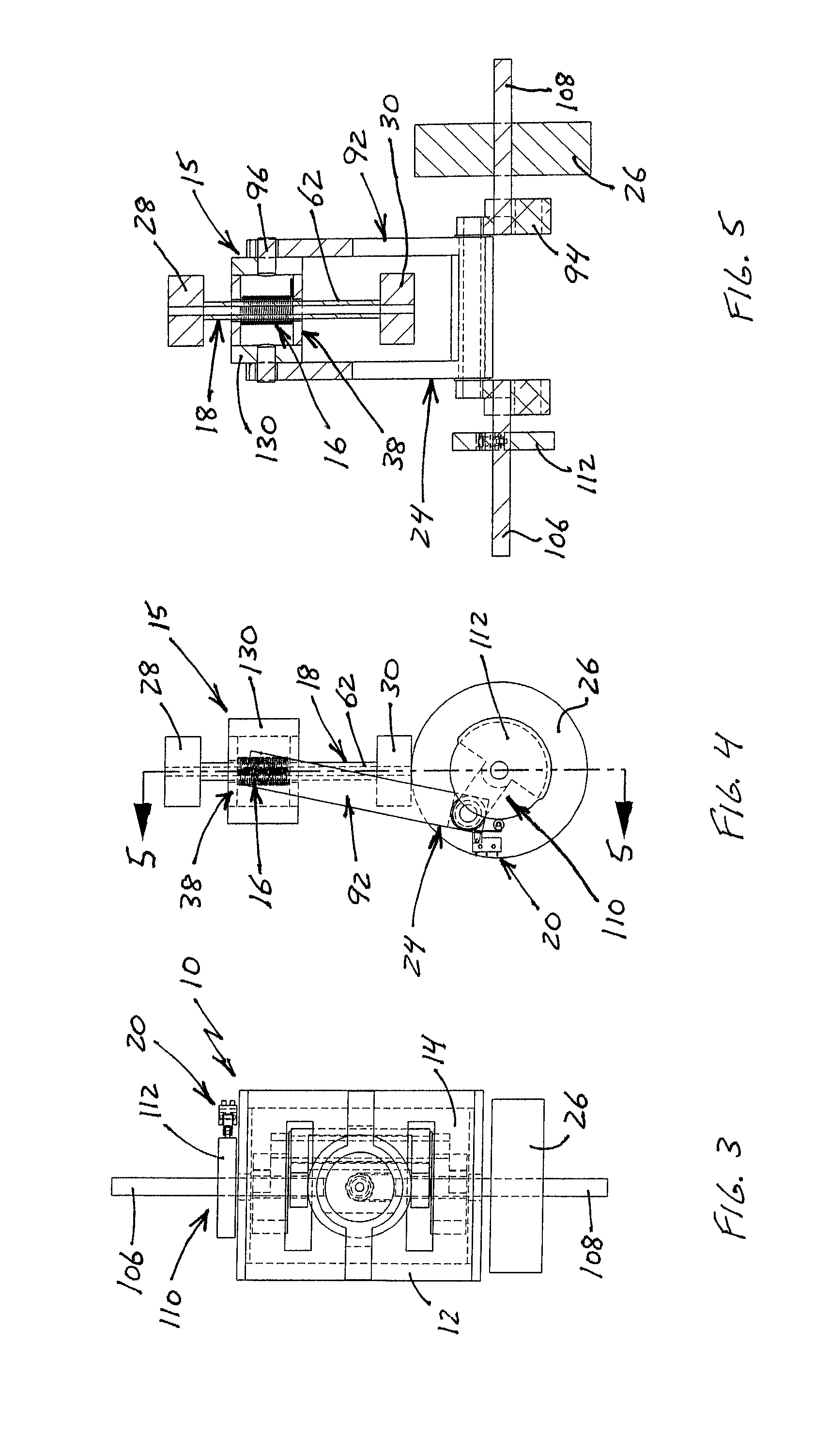
[0043]With reference to the figures where like elements have been given like numerical designations to facilitate the reader's understanding of the present invention, the preferred embodiments of the present invention are set forth below. The enclosed text and drawings are merely illustrative of preferred embodiments and only represent several possible ways of configuring the present invention. Although specific components, materials, configurations and uses are illustrated, it should be understood that a number of variations to the components and to the configuration of those components described herein and in the accompanying figures can be made without changing the scope and function of the invention set forth herein. For instance, the figures and description provided herein are primarily directed to a single motor, however, those skilled in the art will readily understand that this is merely for purposes of simplifying the present disclosure and that the present invention is not...


PUM


Abstract

A magnetically actuated reciprocating motor utilizes the stored energy of rare earth magnets and an electromagnetic field provided by a solenoid to reciprocally drive a solenoid assembly. A converting mechanism, such as a connecting rod and crankshaft, converts the reciprocating motion of the solenoid assembly to power a work object. The solenoid assembly comprises a solenoid having a nonferromagnetic spool with a tubular center section and a coil of wire wrapped around the center section. A magnetic actuator has a permanent magnet at each end of an elongated shaft that is received through the center section of the spool. A switching mechanism switches magnetic polarity at the ends of the solenoid so the solenoid assembly is alternatively repelled and attracted by the permanent magnets. A controlling mechanism interconnecting an output shaft and the switching mechanism provides the timing to switch the polarity of the solenoid and reciprocate the solenoid assembly.

Description

CROSS-REFERENCE TO RELATED APPLICATIONS[0001]This application is a continuation-in-part of U.S. patent application Ser. No. 12 / 832,928 filed Jul. 8, 2010.STATEMENT REGARDING FEDERALLY SPONSORED RESEARCH[0002]Not Applicable.REFERENCE TO A SEQUENCE LISTING, A TABLE OR A COMPUTER PROGRAM LISTING APPENDIX SUBMITTED ON A COMPACT DISC[0003]Not Applicable.BACKGROUND OF THE INVENTION[0004]A. Field of the Invention[0005]The field of the present invention relates generally to reciprocating motors which utilize a drive mechanism to provide power to an output shaft or crankshaft. More particularly, the present invention relates to such motors in which the magnetic repelling and attracting forces of permanent magnets are utilized to reciprocate a solenoid assembly. Even more particularly, the present invention relates to such motors in which the change in direction of the solenoid assembly is obtained by switching the polarity of a solenoid to alternatively repel and attract the solenoid assembl...

Claims


Application Information

Patent Timeline
Patent Type & Authority Patents(United States)
IPC IPC(8): H02K44/00H02K41/00H02K33/00H02K7/06
CPCH02K7/075
Inventor GOSVENER, KENDALL C.
Owner GOSVENER KENDALL C
Why Eureka
Try Eureka