Axial gap motor, compressor, motor system, and power generator

a gap motor and compressor technology, applied in the direction of dynamo-electric machines, electrical apparatus, magnetic circuit shapes/forms/construction, etc., can solve the problems of difficult to form amorphous alloys as iron cores, amorphous alloys can only be manufactured in the form, and more than half the amount of domestically used electrical power is consumed to drive rotary electric machines. , to achieve the effect of enhancing the efficiency of the motor, reducing the cost of the motor, and reducing the loss of iron

Active Publication Date: 2011-04-28
HITACHI METALS LTD +1
View PDF10 Cites 25 Cited by
  • Summary
  • Abstract
  • Description
  • Claims
  • Application Information

AI Technical Summary

Benefits of technology

In the present invention, since a wound core (multilayer iron core) obtained by winding an amorphous alloy is used as a stator core, iron loss can be significantly decreased to simultaneously enhance the efficiency of a motor (rotary electric machine) and reduce the cost thereof.
Further, in the present invention, since high magnetic permeability properties of an amorphous alloy is effectively utilized, the performance of a rotary electric machine can be expected to improve. This makes it possible to decrease torque pulsation, keep induced voltage in the shape of a sine wave, and increase the degree of freedom in design although these could not be easily achieved by a conventional axial gap motor that uses an amorphous alloy. Consequently, high-performance and economical electromagnetic products can be provided at low cost.

Problems solved by technology

Further, more than half the amount of domestically used electrical power is consumed to drive rotary electric machines.
Therefore, the amorphous alloys can only be manufactured in the form of a thin foil strip (ribbon-shaped).
This makes it difficult to form the amorphous alloys as an iron core.
Consequently, the amorphous alloys have not been used for the aforementioned electromagnetic products.
However, these materials have lower magnetic permeability than a commonly used silicon steel sheet, and suffer from significant iron loss.
Therefore, the use of these materials makes it difficult to reduce the size of the axial gap rotary electric machine.
More specifically, magnetic flux obtained from the surfaces of opposing magnets separated by a gap cannot be effectively attracted to the core because the core's cross-sectional area in a plane perpendicular to a winding axis remains constant in any axial cross section.
It means that the coil winding space is limited to reduce the degree of freedom in design.

Method used


Image

  • Axial gap motor, compressor, motor system, and power generator
  • Axial gap motor, compressor, motor system, and power generator
  • Axial gap motor, compressor, motor system, and power generator

Examples


first embodiment

An axial gap motor according to a first embodiment of the present invention will now be described with reference to FIGS. 1A to 4B.

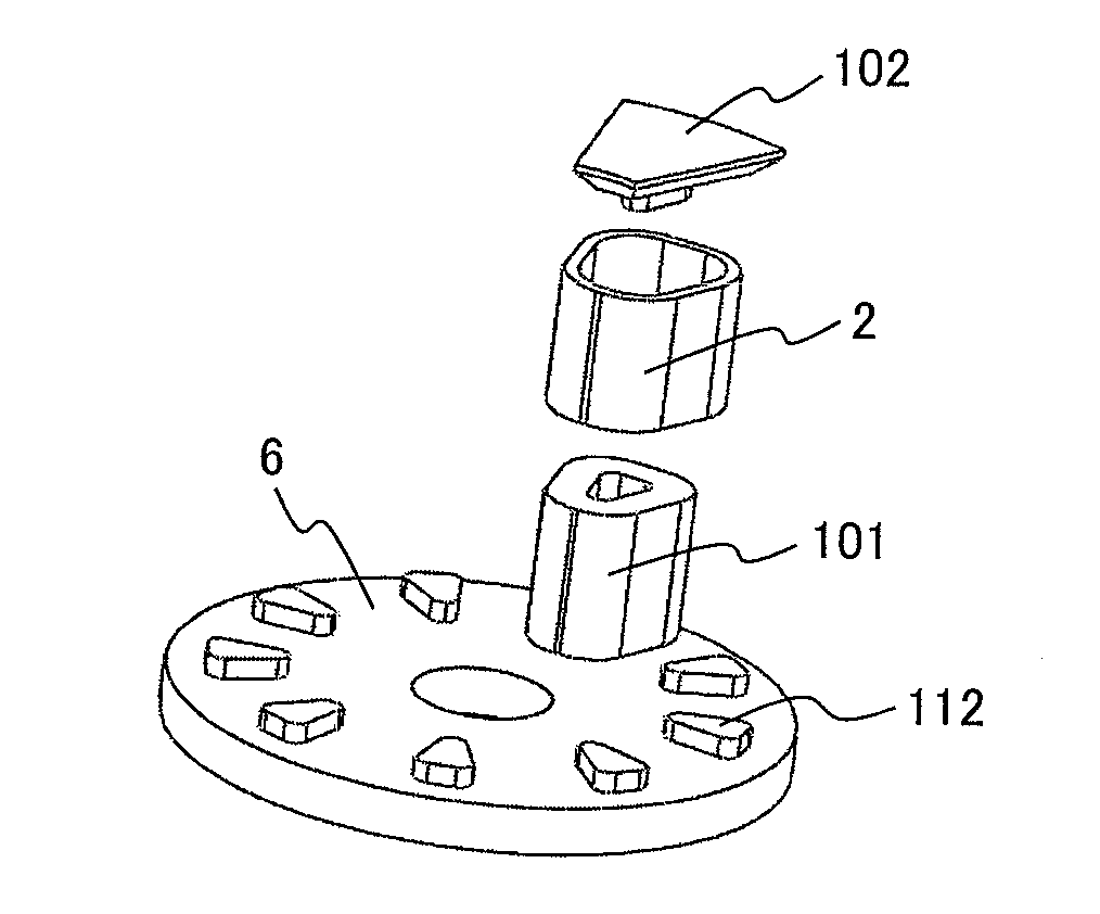
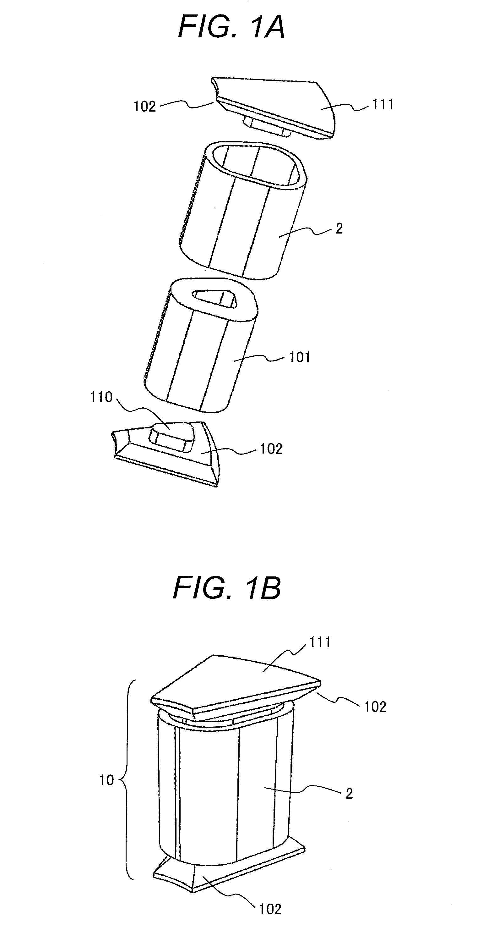
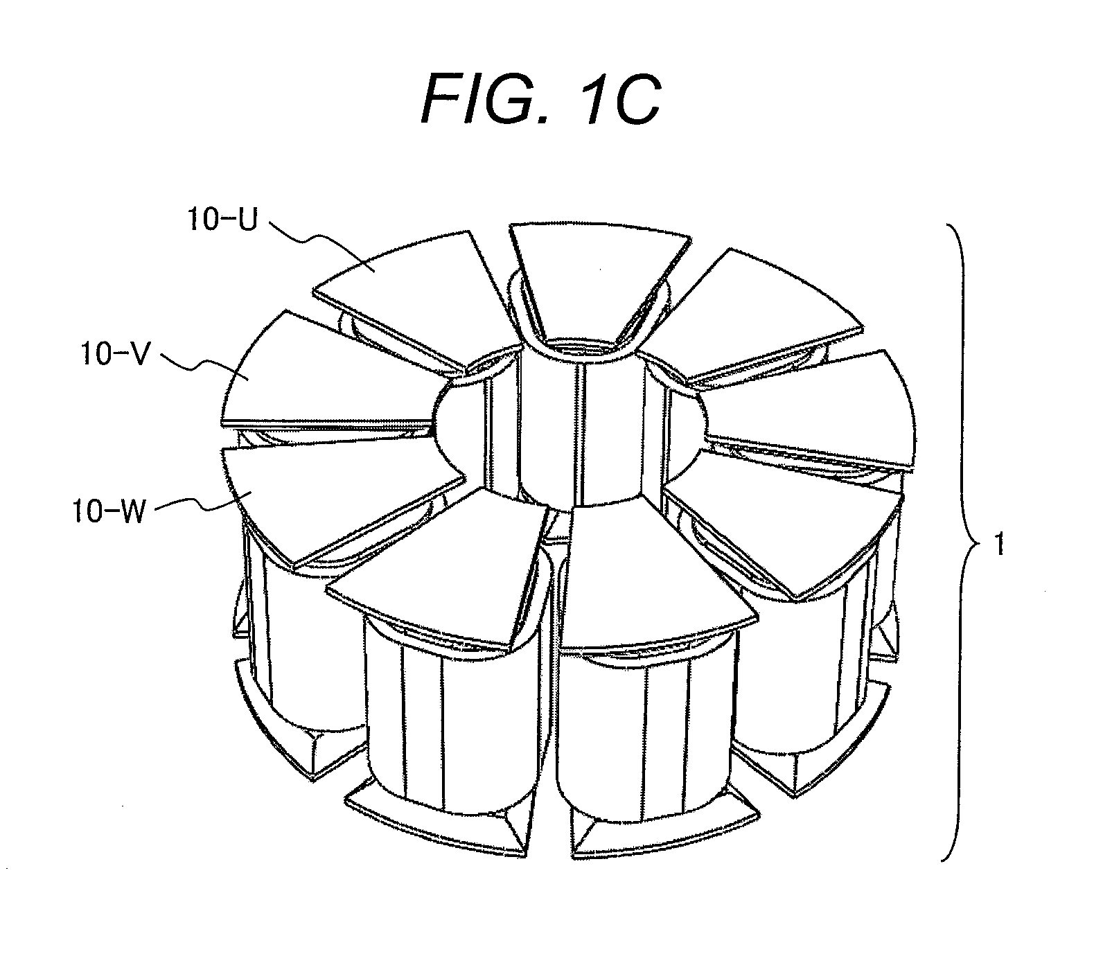
FIGS. 1A and 1B are diagrams illustrating the configuration of a stator tooth of the axial gap motor according to the first embodiment of the present invention. The stator tooth 10 includes a stator core and a stator coil 2, which is disposed around the stator core. The stator core includes a stator tooth body 101 and a stator tooth end 102, and is prepared by using a wound amorphous core and a compact made of a powder magnetic core. In the present embodiment, the stator tooth end 102 is disposed on both ends of the stator tooth body 101. Further, the present embodiment uses a wound amorphous core for the stator tooth body 101. As the wound amorphous core has a constant cross-sectional shape in a plane perpendicular to the winding axis, the stator tooth body 101 also has a constant cross-sectional shape and area in a plane perpendicular to the axial dire...

second embodiment

The axial gap motor according to a second embodiment of the present invention will now be described with reference to FIGS. 5A and 5B.

In the first embodiment, it is assumed that the axial gap motor has a rotor on both ends. More specifically, the first embodiment uses a stator that is obtained by attaching a stator tooth end, which is made of a powder magnetic core compact, to both the upper and lower axial ends of a stator tooth body made of an amorphous foil strip winding. Further, the rotor is disposed on each axial end of the stator. In the second embodiment, it is assumed that the axial gap motor has a rotor on only one axial end of a stator as shown in FIGS. 5A and 5B.

Referring to FIG. 5A, a stator tooth is combined with a stator yoke (axial gap motor stator yoke) 6. The stator tooth includes the stator tooth body 101, one unit of the stator tooth end 102, and the stator coil 2, which have been described in connection with the first embodiment. The stator tooth body 101 is pro...

third embodiment

The axial gap motor according to a third embodiment of the present invention will now be described with reference to FIGS. 6 and 8.

In the foregoing embodiments, it is assumed that the stator core is configured by using a wound amorphous core for the stator tooth body. In the third embodiment, it is assumed that the stator core is configured by using a wound amorphous core for the stator tooth end. As mentioned earlier, the shape of the cross section of the wound amorphous core in a plane perpendicular to the winding axis remains same in any cross section. Therefore, a thin portion of the stator tooth end that has a constant cross-sectional shape in a plane perpendicular to the axial direction is configured by a narrow wound amorphous core, whereas the remaining portion of the stator tooth end (a portion of the stator tooth end that joins to the stator tooth body) and the stator tooth body are formed by a powder magnetic core.

An example shape of the stator core will now be described ...


PUM


Abstract

The present invention provides a low-iron-loss (high-efficiency) and low-cost axial gap motor that includes a high-quality soft magnetic material placed at an appropriate position, reduces torque pulsation, keeps induced voltage in the shape of a sine wave, and increases the degree of freedom in design. The axial gap motor includes a stator having stator teeth; and a rotor being opposed to the stator with a gap in an axial direction of the stator. Each of the stator teeth includes a stator tooth body, a stator tooth end joined to at least one axial-direction end of the stator tooth body, and a stator coil disposed around the stator tooth body. The stator tooth body includes a wound core comprised of a multi-layered amorphous foil strip winding. The stator tooth end is formed by a compact made of a powder magnetic core, and includes an opposed surface to the rotor. A cross-sectional area of the stator tooth end perpendicular to an axis of the amorphous foil strip winding is larger than a cross-sectional area of the stator tooth body perpendicular to the axis of the amorphous foil strip winding.

Description

CLAIM OF PRIORITYThe present application claims priority from Japanese Patent Application JP 2009-243237 filed on Oct. 22, 2009, the content of which is hereby incorporated by reference into this application.FIELD OF THE INVENTIONThe present invention relates to an axial gap motor having gap in axial direction, and more particularly to the stator structure of the axial gap motor. The present invention also relates to an electromagnetic product that includes the axial gap motor.BACKGROUND OF THE INVENTIONIn recent years, it has become important that, for example, industrial devices, home electrical appliances, and automotive parts provide increased energy savings. Electrical power currently generated at domestic power stations such as thermal power stations, hydroelectric power stations, nuclear power stations, or wind power stations is mostly generated with a rotary electric machine (power generator). Further, more than half the amount of domestically used electrical power is consum...

Claims


Application Information

Patent Timeline
Patent Type & Authority Applications(United States)
IPC IPC(8): H02K1/14
CPCH02K21/24H02K1/148
Inventor ENOMOTO, YUJIWANG, ZHUONANMASAKI, RYOSOITABASHI, HIROMITSUIDE, KAZUMASA
Owner HITACHI METALS LTD
Why Eureka
Try Eureka