Pneumatic rotary tool

a rotary tool and pneumatic technology, applied in the field of pneumatic rotary tools, can solve the problems of such as steel, and reducing the rigidity of plastic as compared with a strong metal, so as to reduce the amount of air entering the tool, reduce the weight and cost, and efficiently control the torque output of the motor

Inactive Publication Date: 2008-07-29
S P AIR
View PDF77 Cites 28 Cited by
  • Summary
  • Abstract
  • Description
  • Claims
  • Application Information

AI Technical Summary

Benefits of technology

[0006]Among the several objects and features of the present invention may be noted the provision of a pneumatic rotary tool which weighs and costs less due to a primarily plastic housing; the provision of such a tool having a plastic housing which resists misalignment of internal components under impact; the provision of such a tool which is comfortable to grip; the provision of such a tool having a plastic housing which fixes components without fasteners; the provision of such a pneumatic rotary tool which regulates torque between four discrete levels adjustable by the user; the provision of such a pneumatic rotary tool which throttles pressurized air as it enters the tool to efficiently control torque output of the motor by reducing how much air enters the tool; and the provision such of a pneumatic rotary tool which reduces back pressure within the motor and increases motor efficiency.
[0011]In another aspect of the present invention, a pneumatic rotary tool comprises a housing and a grip. The grip extends downwardly from the housing for allowing a user to grasp and hold the tool securely. The grip further comprises an outer layer of soft material formed to cushion and ease pressure on the user's hand and increase friction between the grip and the user.

Problems solved by technology

These tools are strong and durable due to their metallic construction, although the all-metal construction makes them both somewhat heavy and costly.
One difficulty in the design of such a tool is the reduced rigidity of plastic as compared with a strong metal, such as steel.
For instance, should a plastic tool fall against a hard surface, a metallic air motor inside the tool may shift and become misaligned, or canted, with respect to the housing and the output shaft, rendering the tool unusable.
This problem has led tool manufacturers to create complex internal motor casings designed to inhibit the motor from canting in the housing.
The cylinder, back head and bore are of unitary construction, making a closed end cylinder significantly more difficult to manufacture.
Therefore, these casings are expensive to manufacture, which may mitigate the cost benefit of using lighter and less costly materials, such as plastic, for other parts.
Such a design is inefficient because it uses the maximum flow of pressurized air to power the tool, while operating below its maximum power.

Method used


Image

  • Pneumatic rotary tool
  • Pneumatic rotary tool
  • Pneumatic rotary tool

Examples


Embodiment Construction

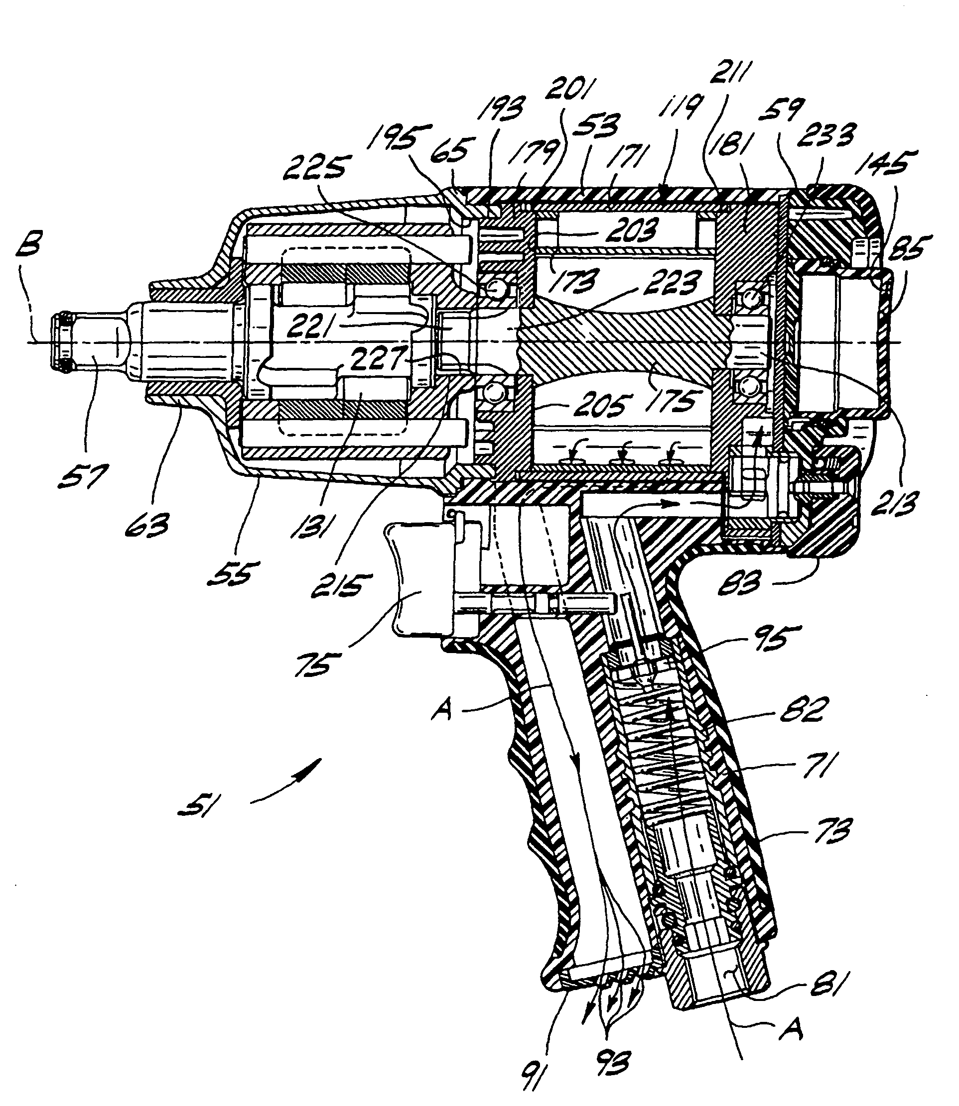
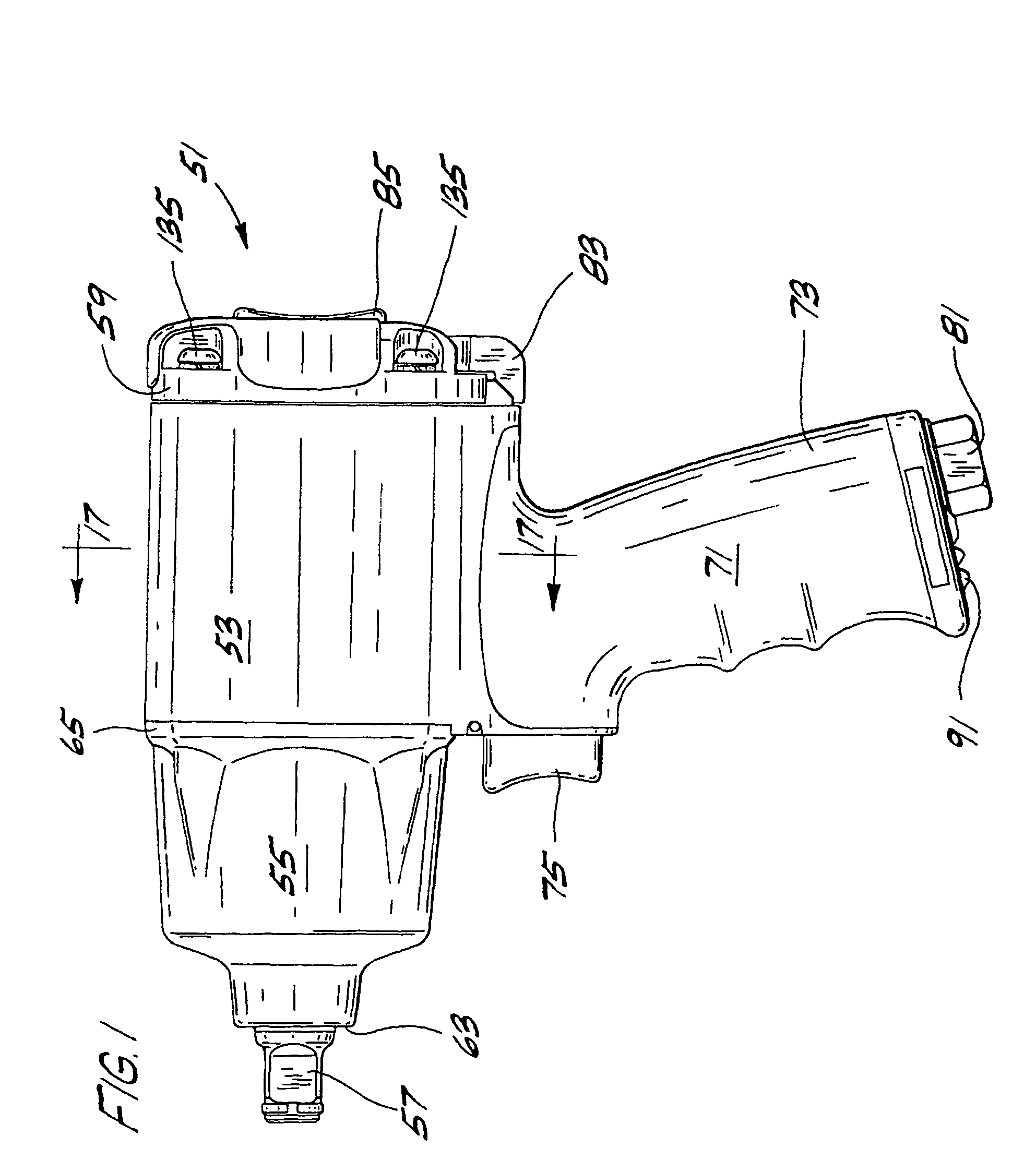
[0046]Referring now to the drawings and specifically to FIG. 1, a pneumatic rotary tool of the present invention is generally indicated at 51. The tool includes a housing 53, a Maurer Mechanism casing 55 at the front of the housing, an output shaft 57 and an end cover 59 mounted on the rear of the housing 53. The casing 55 may be considered part of the housing 53, due to the generally uniform interface between the housing and casing, which creates the appearance of one continuous profile when viewing the tool 51. The output shaft 57 extends from an front end 63 of the Maurer Mechanism casing 55. A back end 65 of the Maurer Mechanism casing 55 engages the housing 53. The tool 51 further comprises a grip 71 extending downwardly from the housing 53, allowing a user to grasp and hold the tool securely. The grip 71 has an additional outer layer 73 of soft material, such as rubber, to cushion and ease pressure on the user's hand, while increasing friction between the grip 71 and the user,...


PUM

PropertyMeasurementUnit
torqueaaaaaaaaaa
internal diameteraaaaaaaaaa
forcesaaaaaaaaaa

Abstract

A pneumatic rotary tool has a housing formed primarily from plastic so that the weight and price of the tool are substantially reduced. The air motor is formed for economic assembly while permitting greater structural stability should the housing deflect under an impact. The tool includes a torque selector which controls the amount of pressurized air allowed to enter the air motor, thereby controlling the torque output of the motor. The user may adjust the torque selector to a number of set positions which correspond to discrete torque values. The tool additionally incorporates early and late stage exhaust ports, so that backpressure within the air motor does not slow motor rotation or decrease tool power.

Description

BACKGROUND OF THE INVENTION[0001]This invention generally relates to pneumatic rotary tools and more particularly to an improved pneumatic rotary tool having a plastic housing and a variable torque design for efficient use of pressurized air.[0002]The invention is especially concerned with a powered tool that rotates an output shaft with a socket for turning a fastener element such as a bolt or nut. Tools of this type are frequently used in automotive repair and industrial applications. Conventionally, pneumatic rotary tools comprise a metallic outer housing with multiple metallic internal parts. These tools are strong and durable due to their metallic construction, although the all-metal construction makes them both somewhat heavy and costly. Pressurized air flowing through the tool powers tools of this type. As the air expands within the tool, it induces motion of an internal motor, powering the tool.[0003]It is an aim of tool manufacturers to provide a pneumatic rotary tool that ...

Claims


Application Information

Patent Timeline
Patent Type & Authority Patents(United States)
IPC IPC(8): B25D9/00B25D15/00B25D9/14B25B21/00B25B21/02B25B23/14B25B23/145B25F5/00
CPCB25B21/02B25B23/1405B25F5/00B25B23/1453Y10T16/44Y10T29/49826
Inventor IZUMISAWA, OSAMUYAMAMOTO, KUNIHIRO
Owner S P AIR
Why Eureka
Try Eureka