Hydro turbine

a hydro-turbine and water-cooled technology, applied in the direction of motors, electrical equipment, control systems, etc., can solve the problems of low efficiency, no means are disclosed however for producing useful work from the external flow surrounding the housing, and the funnel appears to serve no useful purpose, so as to reduce the back pressure and increase the overall performance of the turbine

Inactive Publication Date: 2006-12-12
LAMONT JOHN S
View PDF9 Cites 39 Cited by
  • Summary
  • Abstract
  • Description
  • Claims
  • Application Information

AI Technical Summary

Benefits of technology

[0019]The use of a diverter which slopes inwardly at the free end of the divergent cone at the exit end of the housing causes acceleration of the flow exiting the housing to reduce back pressure and increase the overall performance of the turbine unlike any known prior art devices.

Problems solved by technology

Energy from the surrounding fluid flow is typically not captured and accordingly a low efficiency results due to the lost energy not harnessed.
No means are disclosed however for producing useful work from the external flow surrounding the housing.
In one embodiment a funnel of fabric material is provided about the housing however the funnel appears to serve no useful purpose as the funnel diverges as it extends rearwardly beyond the exit end of the housing.
Furthermore the fabric material lacks durability and does not provide an even flow about the periphery of the exit end of the housing due to its flexible nature.

Method used


Image

  • Hydro turbine
  • Hydro turbine
  • Hydro turbine

Examples


Embodiment Construction

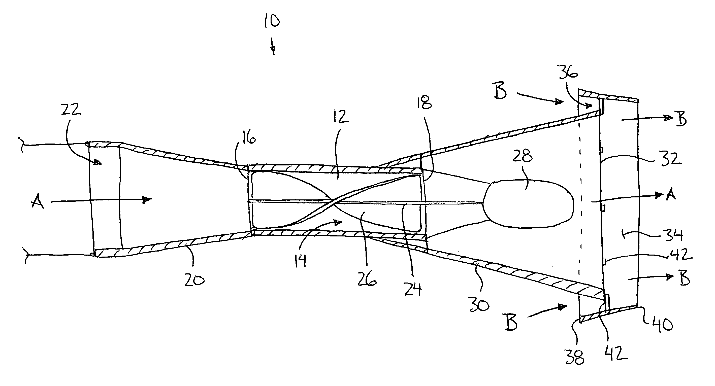
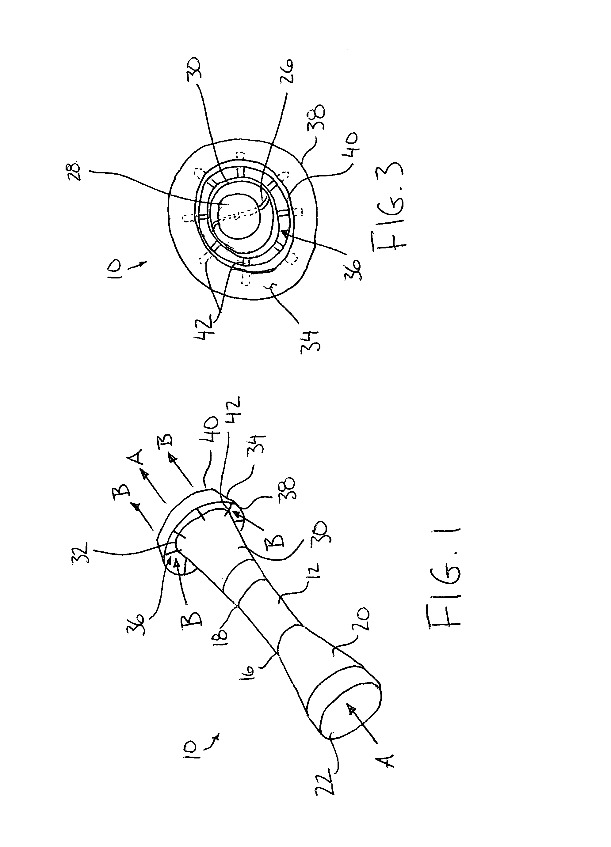
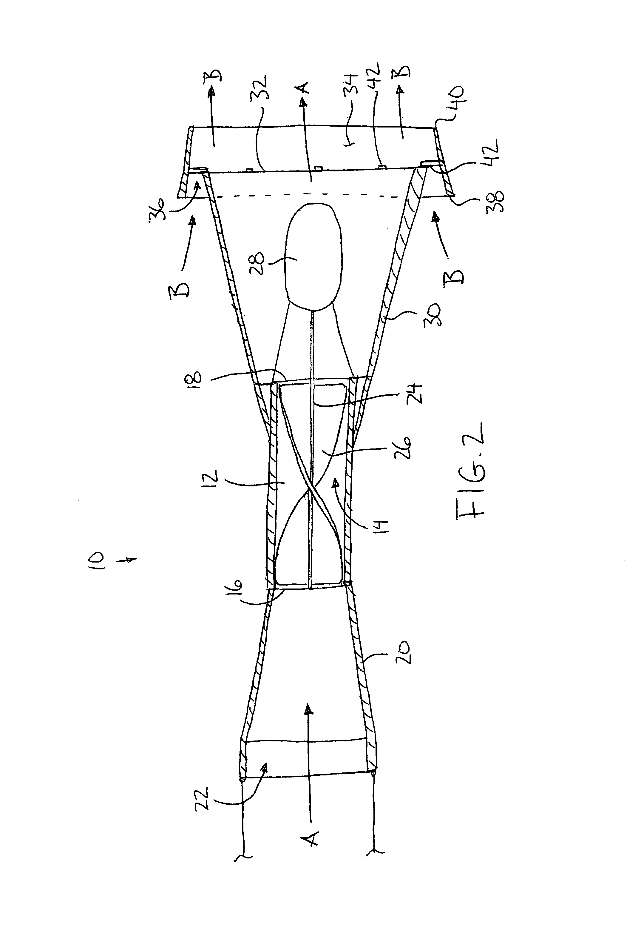
[0038]Referring to the accompanying drawings there is illustrated a turbine generally indicated by reference numeral 10. The turbine 10 is particularly useful for converting energy of a water current into useful electrical power when submerged in a river or stream.

[0039]The turbine includes a housing 12 having an elongate tubular body. The body is hollow so as to define an opening 14 extending through the housing in the longitudinal direction thereof between the entry end 16 and the exit end 18 thereof. When submerged in a river or stream, the current of water is received into the entry end and passes through the housing to be subsequently released through the exit end thereof.

[0040]A convergent cone 20 is supported on the entry end of the housing which converges from a mouth 22 at an inward incline, reducing in diameter towards the entry end 16 of the housing with which it communicates. The convergent cone collects a large volume of water to be directed into the housing.

[0041]A sha...


PUM


Abstract

A water driven turbine has a divergent cone coupled to the exit end of the housing in which diameter of the cone increases with increasing distance from the exit end of the housing. A diverter formed of rigid material surrounds the free end of the cone and defines an annular space therebetween through which a flow of water passes to accelerate the flow exiting the turbine housing. The diverter is shorter in the length than the divergent cone and longitudinally overlaps the divergent cone. The diverter also has straight walls which are sloped to extend in the longitudinal direction away from the exit end of the housing at an inward incline between the leading end and the trailing end thereof.

Description

[0001]This application hereby claims the benefit under 35 U.S.C. Section 119(e) of U.S. provisional application 60 / 526,601 filed Dec. 4, 2003.FIELD OF THE INVENTION[0002]The present invention relates generally to an underwater turbine.BACKGROUND OF THE INVENTION[0003]Various designs of turbines are known for capturing useful energy from wind and water currents. These turbines typically include a housing with an opening extending therethrough for receiving the fluid flow. Rotating blades are supported within the opening to drive a generator and the like using energy converted from the fluid flow impacting the blades. Energy from the surrounding fluid flow is typically not captured and accordingly a low efficiency results due to the lost energy not harnessed.[0004]U.S. Pat. No. 4,025,220 to Thompson discloses an underwater turbine intended to capture energy from water currents. No means are disclosed however for producing useful work from the external flow surrounding the housing. In ...

Claims


Application Information

Patent Timeline
Patent Type & Authority Patents(United States)
IPC IPC(8): F03B3/04F03B3/16F03D7/00
CPCF03B3/04F03B3/16F05B2250/25Y02E10/223Y10S415/906Y10S415/908Y02E10/20
Inventor LAMONT, JOHN S.
Owner LAMONT JOHN S
Why Eureka
Try Eureka