System and method for production of reservoir fluids

Inactive Publication Date: 2011-11-17
NGSIP
View PDF5 Cites 38 Cited by
  • Summary
  • Abstract
  • Description
  • Claims
  • Application Information

AI Technical Summary

Benefits of technology

A dual string anchor may be disposed with the first tubing string to limit the movement of the second tubing string. The second tubing string may be removably attached with the dual string anchor with an on-off tool without disturbing the first tubing string. A one-way valve may also be used to allow reservoir fluids to flow into the first tubing string

Problems solved by technology

The resulting reduced back pressure on the

Method used


Image

  • System and method for production of reservoir fluids
  • System and method for production of reservoir fluids
  • System and method for production of reservoir fluids

Examples


Embodiment Construction

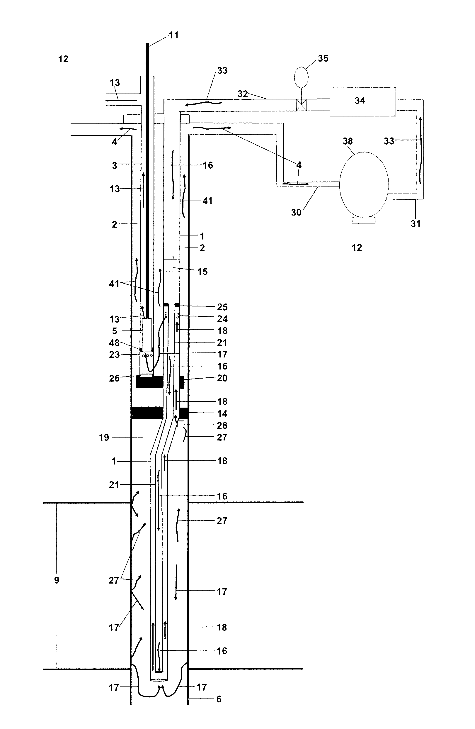
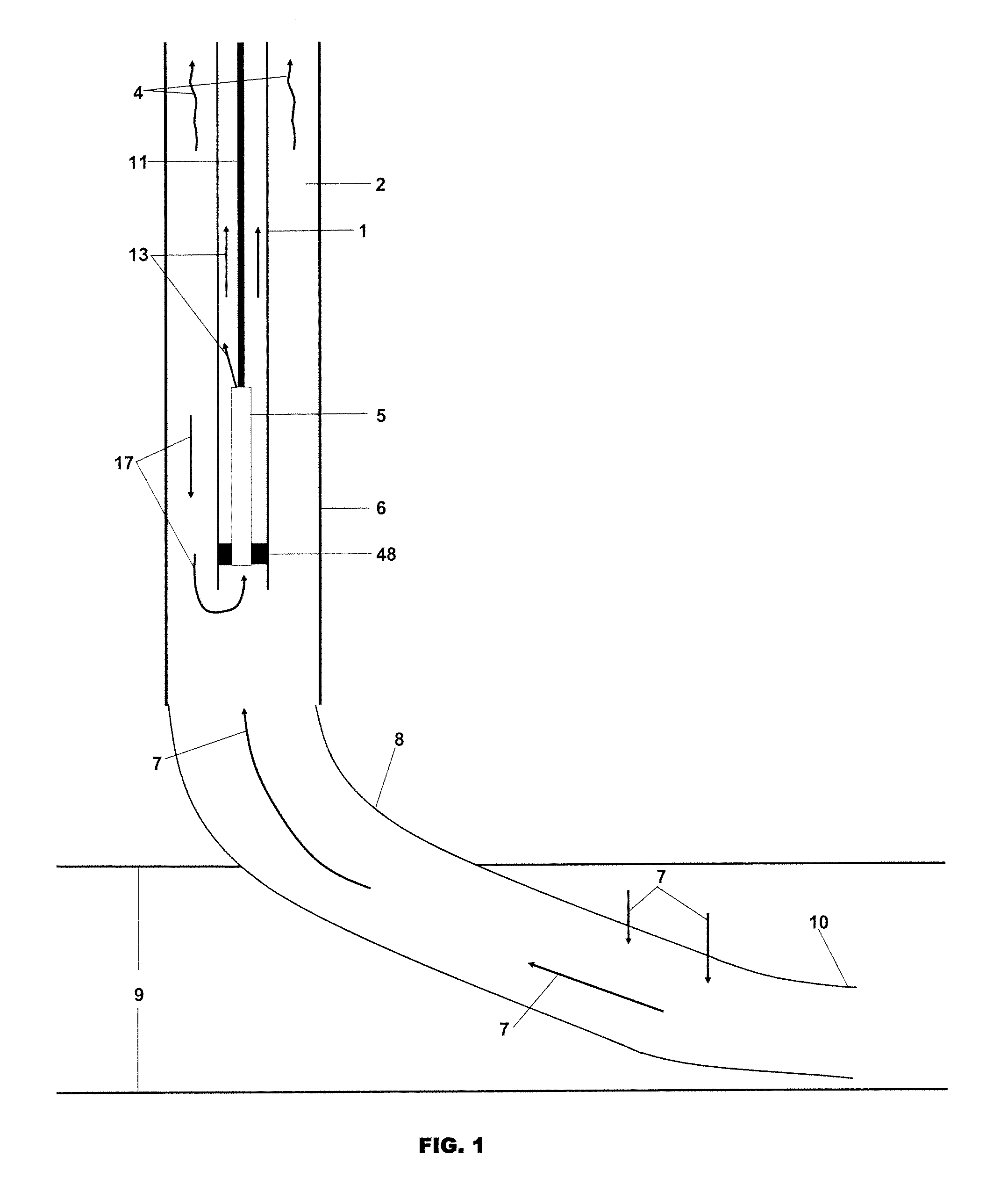
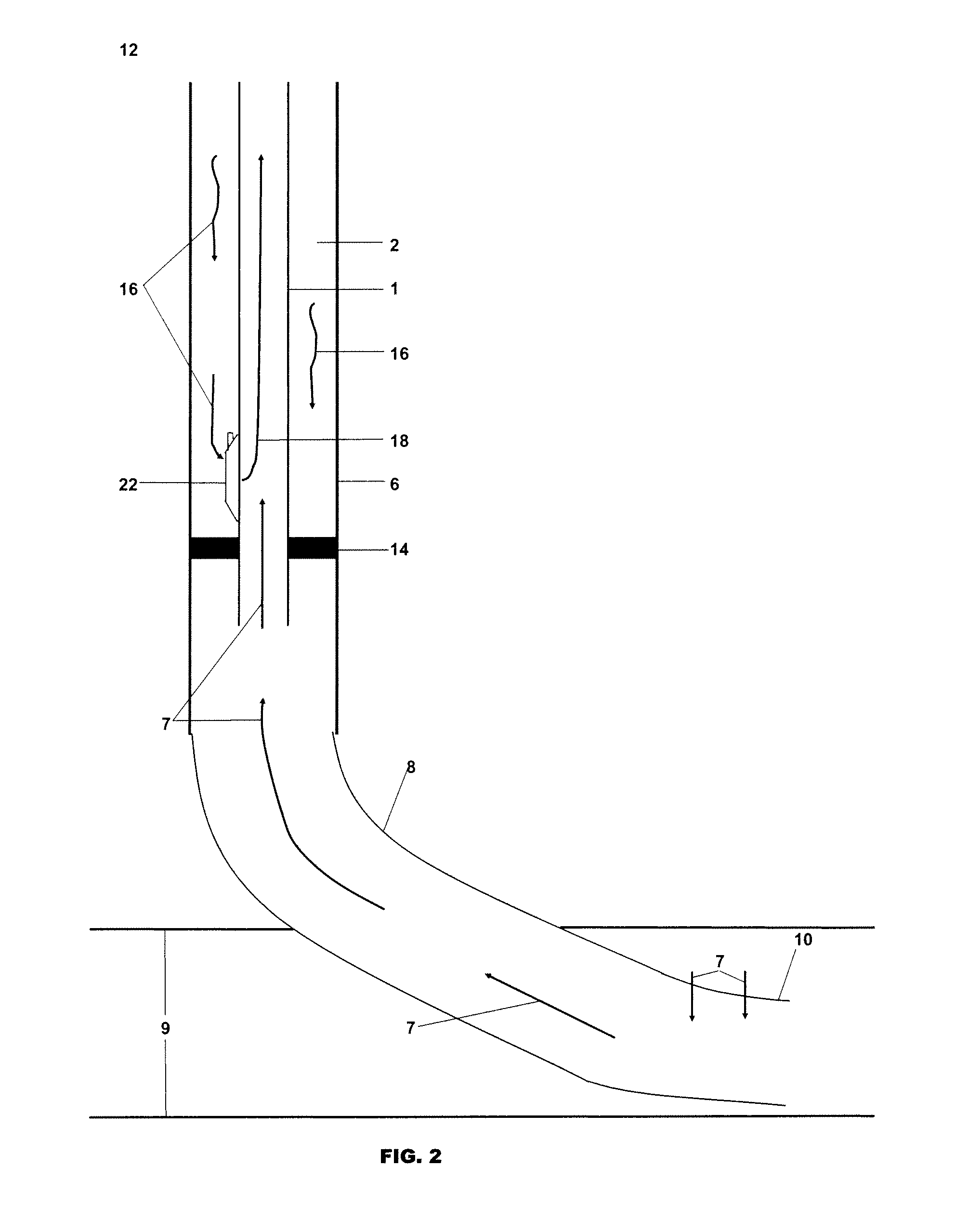
FIG. 1 shows one example of a conventional rod pump system of the prior art in a directional or horizontal wellbore. As set out in FIG. 1, tubing 1, which contains pumped liquids 13 is mounted inside a casing 6. A pump 5 is connected at the end of tubing 1 in a seating nipple 48 nearest the reservoir 9. Sucker rods 11 are connected from the top of pump 5 and continue vertically to the surface 12. Casing 6, cylindrical in shape, surrounds and may be coaxial with tubing 1 and extends below tubing 1 and pump 5 on one end and extends vertically to surface 12 on the other end. Below casing 6 is curve 8 and lateral 10 which is drilled through reservoir 9.

The process is as follows: reservoir fluids 7 are produced from reservoir 9 and enter lateral 10, rise up curve 8 and casing 6. Because reservoir fluids 7 are usually multiphase, they separate into annular gas 4 and liquids 17. Annular gas 4 separates from reservoir fluids 7 and rises in annulus 2, which is the void space formed between t...


PUM


Abstract

An artificial lift system removes reservoir fluids from a wellbore. A gas lift system is disposed in a first tubing string anchored by a packer, and a downhole pump, or alternative plunger lift, may be positioned with a second tubing string. A dual string anchor may be disposed with the first tubing string to limit the movement of the second tubing string. The second tubing string may be removably attached with the dual string anchor with an on-off tool without disturbing the first tubing string. A one-way valve may also be used to allow reservoir fluids to flow into the first tubing string in one direction only. The second tubing string may be positioned within the first tubing string and the injected gas may travel down the annulus between the first and second tubing strings. A bi-flow connector may anchor the second string to the first string and allow reservoir liquids in the casing tubing annulus to pass through the connector to the downhole pump. Injected gas may be allowed to pass vertically through the bi-flow connector to lift liquids from below the downhole pump to above the downhole pump. The bi-flow connector prevents the downwardly injected gas from interfering with the reservoir fluids flowing through the bi-flow connector. In another embodiment, gas from the reservoir lifts reservoir liquids from below the downhole pump to above the downhole pump. A first tubing string may contain a downhole pumping system or alternative plunger lift above a packer assembly. A concentric tubing system below the packer may lift liquids using the gas from the reservoir.

Description

STATEMENT REGARDING FEDERALLY SPONSORED RESEARCH OR DEVELOPMENTN / AREFERENCE TO MICROFICHE APPENDIXN / ABACKGROUND OF THE INVENTION1. Field of the InventionThis invention relates to production systems and methods deployed in subterranean oil and gas wells.2. Description of the Related ArtMany oil and gas wells will experience liquid loading at some point in their productive lives due to the reservoir's inability to provide sufficient energy to carry wellbore liquids to the surface. The liquids that accumulate in the wellbore may cause the well to cease flowing or flow at a reduced rate. To increase or re-establish the production, operators place the well on artificial lift, which is defined as a method of removing wellbore liquids to the surface by applying a form of energy into the wellbore. Currently, the most common artificial lift systems in the oil and gas' industry are down-hole pumping systems, plunger lift systems, and compressed gas systems.The most popular form of down-hole p...

Claims


Application Information

Patent Timeline
IPC IPC(8): E21B43/00
CPCE21B17/18E21B43/305E21B43/122E21B33/12
Inventor MAZZANTI, DARYL V.
Owner NGSIP
Why Eureka
Try Eureka