Spray actuating mechanism for a dispensing canister

a technology of spray valve and actuating mechanism, which is applied in the directions of liquid dispensing, packaging, transportation and packaging, etc., can solve the problems of difficult assembly and achieve the effect of simple functionality and economics

Active Publication Date: 2007-04-17
SUMMIT PACKAGING SYST INC
View PDF45 Cites 63 Cited by
  • Summary
  • Abstract
  • Description
  • Claims
  • Application Information

AI Technical Summary

Benefits of technology

[0009]It is an object of the present invention to provide an economical and easy to manufacture and assemble spray actuator with a minimum number of parts and simple functionality.

Problems solved by technology

Because of their functionality, trigger actuated spray actuators are composed of numerous parts which are firstly very difficult to mold, and secondly and perhaps more importantly, difficult to assemble.

Method used


Image

  • Spray actuating mechanism for a dispensing canister
  • Spray actuating mechanism for a dispensing canister
  • Spray actuating mechanism for a dispensing canister

Examples


Embodiment Construction

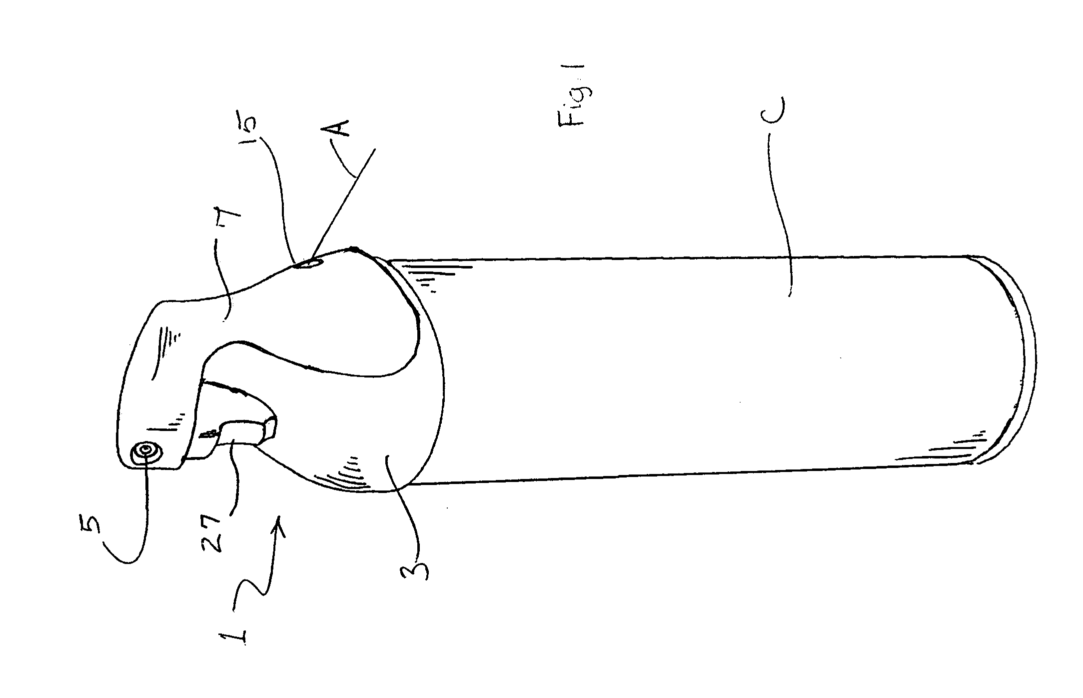
[0025]As illustrated in FIG. 1, a spray aerosol dispensing container according to the present invention comprises a pressurized canister C and a spray actuator mechanism 1. The pressurized canister, or spray can C, contains a product to be dispensed as an aerosol, such as repellents, cleaners, fresheners i.e. any other fluid that may be dispensed as an aerosol. Typically a pressurized gas propellent, such as carbon dioxide, or other suitable gas is dissolved in the product, although any suitable manner of pressurizing the canister may be used.

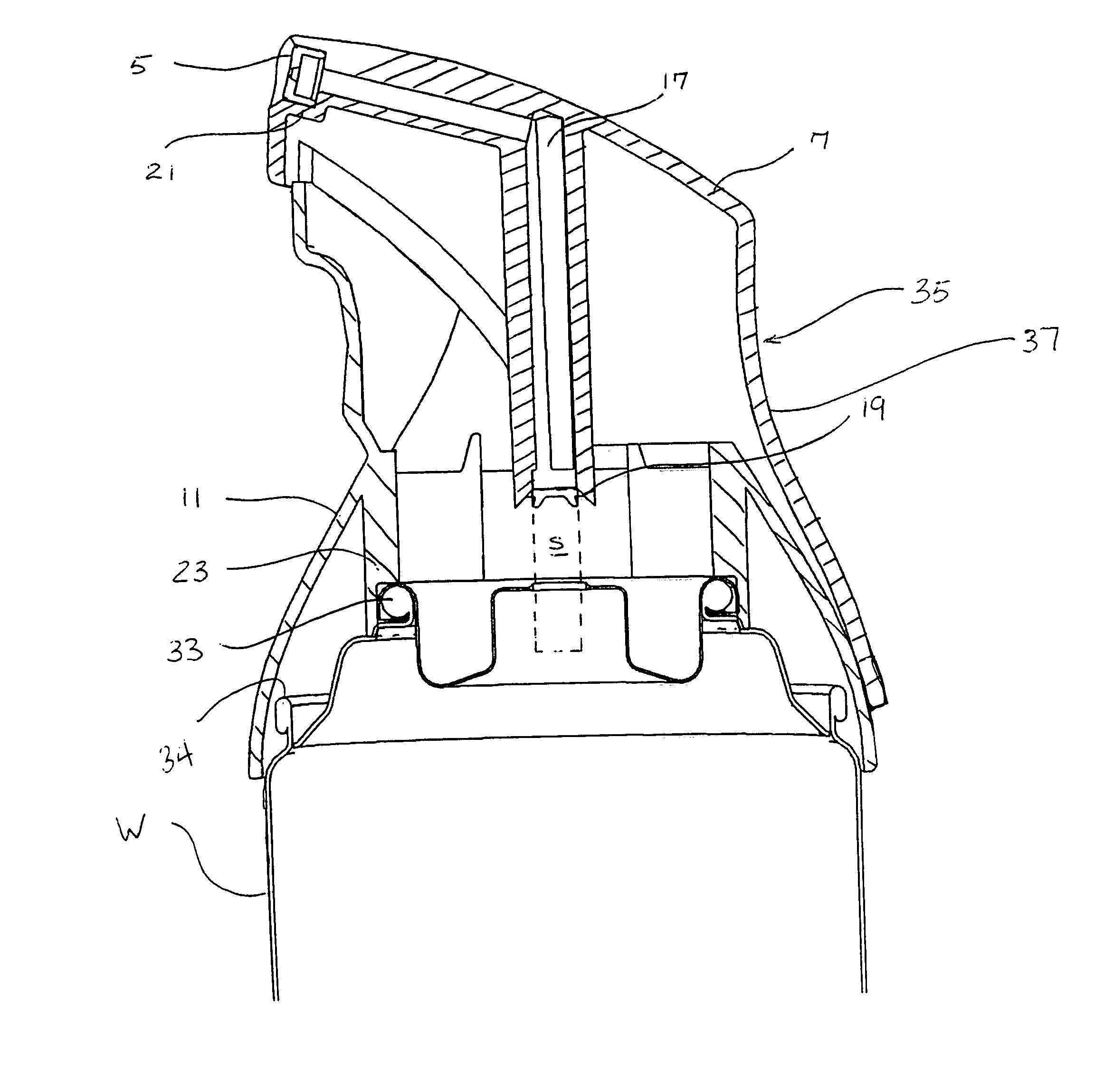
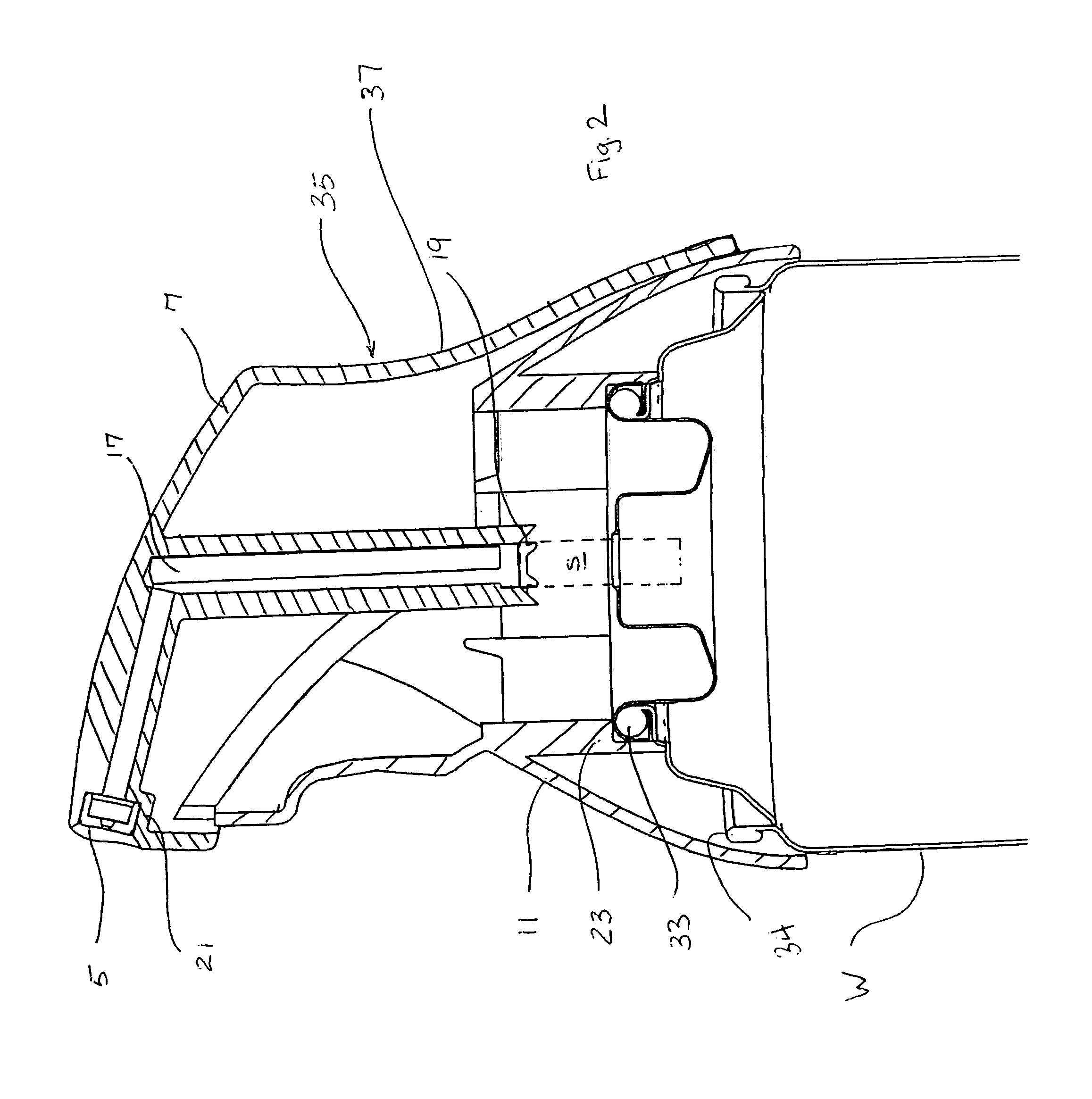
[0026]The actuator 1 mechanism is composed of three main parts to facilitate the manufacture and assembly and lower the cost of producing the actuator 1. The three main parts are the body 3 of the actuator 1, a trigger 7 pivotally secured and supported on the body 3, and a nozzle 5 which may be inserted in a dispensing orifice 21 of the trigger 7 and communicates with a product passage way integrally formed in the actuator 1. Functionally, the ...


PUM


Abstract

A spray actuator for a pressurized aerosol canister that simplifies the mechanical moving parts of a spray actuator to a body and a trigger and a third nozzle piece being inserted at the very end of the product dispensing passage either in the body or the trigger. The moveable trigger rotates about a pivot or hinge point on the body and is biased by engagement with the valve stem or an additional spring return into a neutral unactuated position where the product is not dispensed. When dispensing of the product is desired, the user grasps the actuator and pulls the trigger against the body and overcomes the bias of the valve stem and the valve is actuated as discussed above to dispense the pressurized aerosol product.

Description

FIELD OF THE INVENTION[0001]This invention relates to an actuating mechanism for aerosol product dispensing containers, and more particularly to an aerosol spray valve actuating mechanism for actuating an aerosol spray valve and dispensing the aerosol product from the dispensing container.BACKGROUND OF THE INVENTION[0002]Aerosol dispensing containers generally comprise a pressurized canister within which is stored a product to be dispensed as an aerosol. The canister is pressurized, for example, by a propellant which is generally dissolved within the product. The product is released from the canister upon opening of for example a pressure actuated valve mechanism located in the top of the canister.[0003]The valve mechanism generally comprises a valve stem defining a passage therethrough which communicates with the interior of the canister, and through which product may flow out of the canister when the valve is appropriately actuated. An orifice is often provided in the wall of the ...

Claims


Application Information

Patent Timeline
Patent Type & Authority Patents(United States)
IPC IPC(8): B65D83/00
CPCB65D83/206B65D83/46
Inventor STRAND, TORALF H.
Owner SUMMIT PACKAGING SYST INC
Why Eureka
Try Eureka