Button actuated mechanism for a dispensing canister

a technology of actuating mechanism and aerosol product, which is applied in the directions of liquid dispensing, packaging, transportation and packaging, etc., can solve the problems of difficult assembly and difficult mold assembly, and achieve the effect of simple functionality and economics

Inactive Publication Date: 2007-03-08
SUMMIT PACKAGING SYST
View PDF63 Cites 70 Cited by
  • Summary
  • Abstract
  • Description
  • Claims
  • Application Information

AI Technical Summary

Benefits of technology

[0009] It is an object of the present invention to provide an economical and easy to manufacture and assemble spray actuator with a minimum number of parts and simple functionality.

Problems solved by technology

Because of their functionality, button actuated spray actuators are composed of numerous parts which are, firstly, very difficult to mold and, secondly, and perhaps more importantly, difficult to assemble.

Method used


Image

  • Button actuated mechanism for a dispensing canister
  • Button actuated mechanism for a dispensing canister
  • Button actuated mechanism for a dispensing canister

Examples


Embodiment Construction

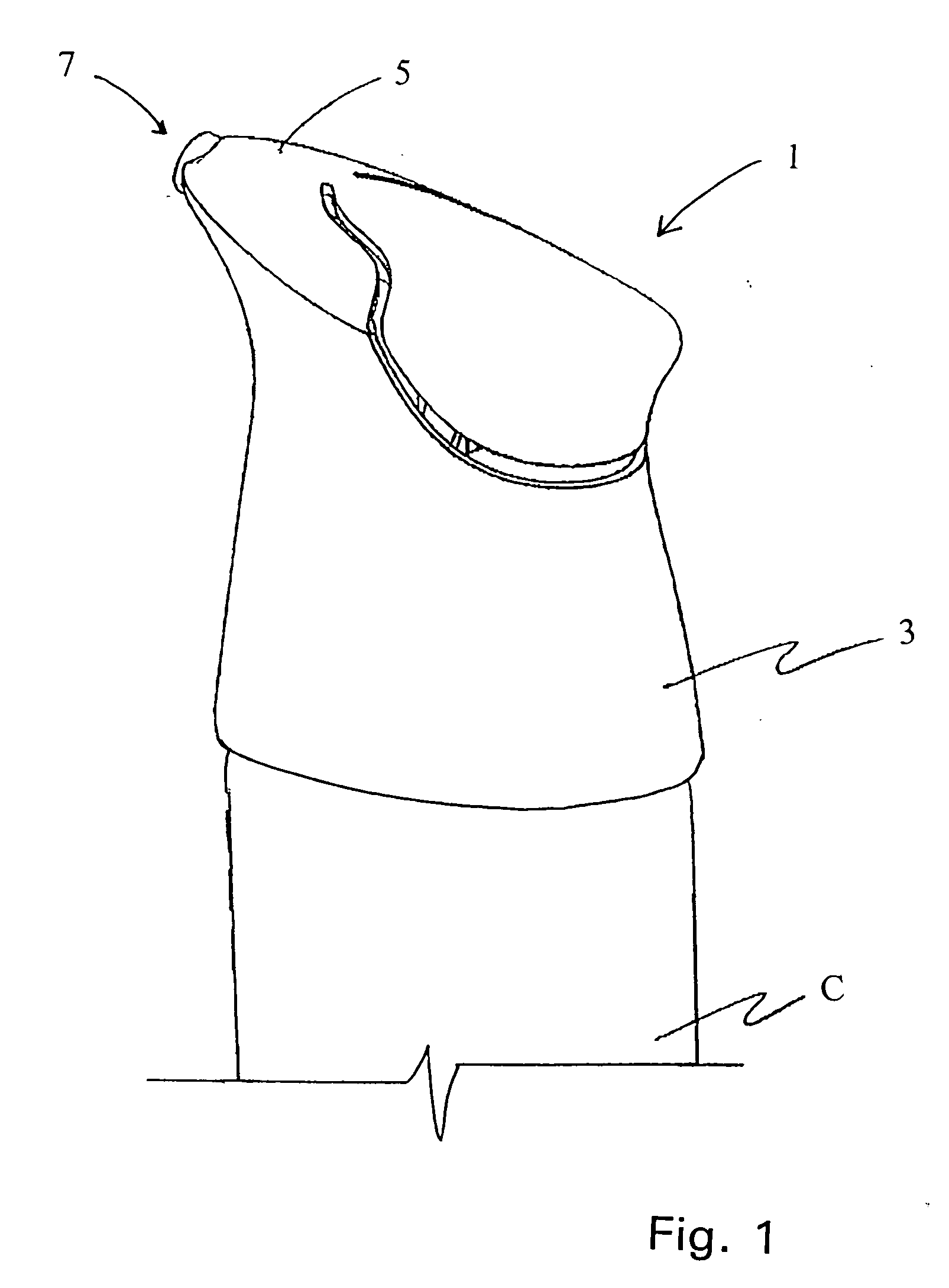
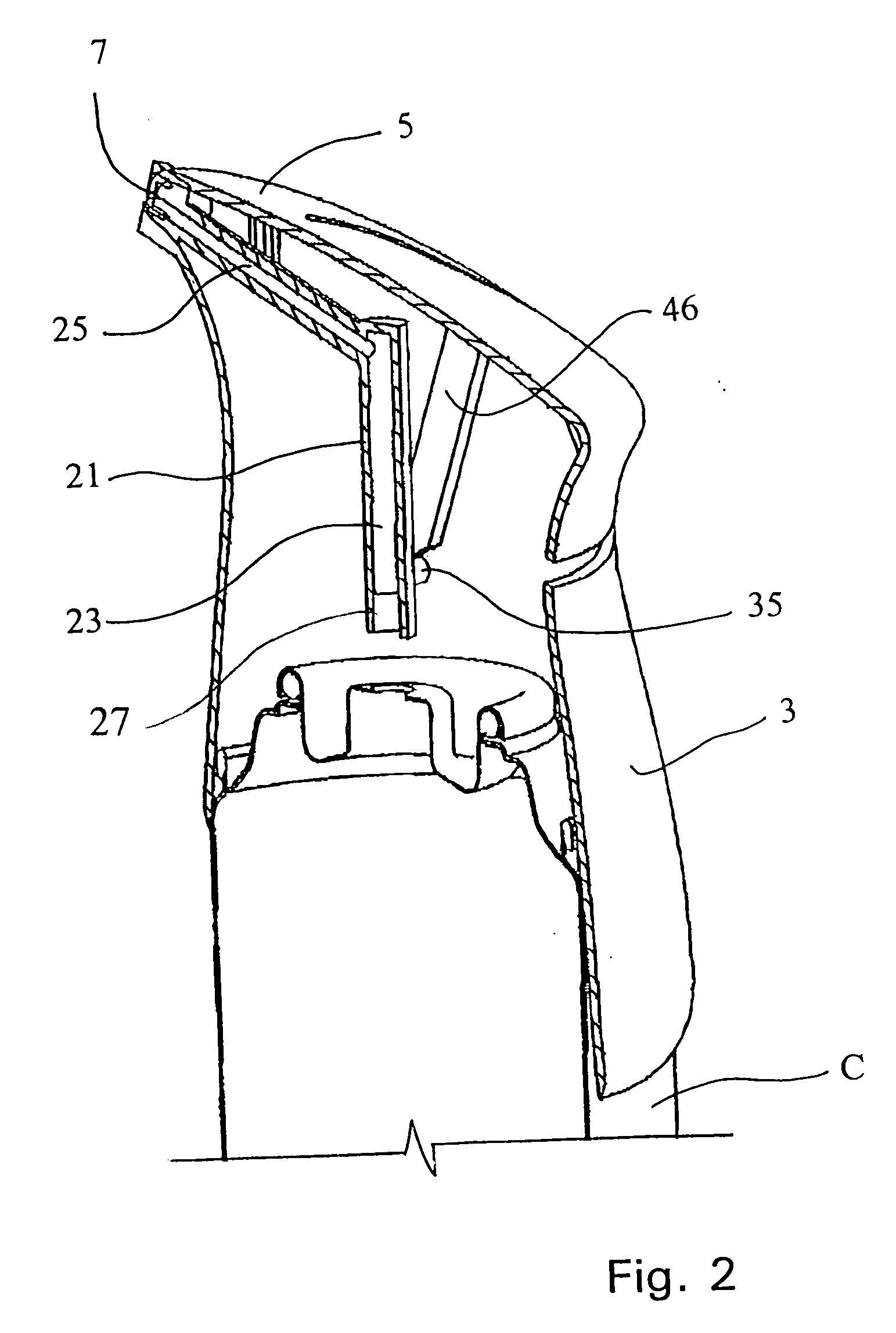
[0041] An embodiment of the present invention is shown in FIGS. 1 to 7 as an aerosol spray actuator mechanism 1 for use in conjunction with a pressurized aerosol spray can C. The actuator mechanism 1 is comprised of three separately molded elements, a main body 3, a button cap 5, and a nozzle 7 as described in further detail below.

[0042] The main body 3 shown separately in FIGS. 4A-B and 5, is a hollow, substantially cylindrical, or conical shell having a sidewall 8 which slightly tapers from a bottom end 9 for engaging the aerosol can C to a top end 11 for supporting the button cap 5. The sidewall 8 is defined about a longitudinal axis A passing through the approximate center of the actuator 1 and the valve stem of the pressurized canister. The taper may include a waist portion 10 which has a smaller diameter than the remainder of the main body 3 relative to the axis A to provide ergonomic grasping of the actuator 1.

[0043] As seen in FIGS. 4A, 4B and 5, the top edge 15 of the bod...


PUM


Abstract

An actuating mechanism for aerosol product dispensing containers, and more particularly to a button actuated aerosol spray valve actuating mechanism for actuating an aerosol spray valve and dispensing the aerosol product from the dispensing container.

Description

FIELD OF THE INVENTION [0001] This invention relates to an actuating mechanism for aerosol product dispensing containers, and more particularly to a button actuated aerosol spray valve actuating mechanism for actuating an aerosol spray valve and dispensing the aerosol product from the dispensing container. BACKGROUND OF THE INVENTION [0002] Aerosol dispensing containers generally comprise a pressurized canister within which is stored a product to be dispensed as an aerosol. The canister is pressurized, for example, by a propellant which is generally dissolved within the product. The product is released from the canister upon opening of, for example, a pressure actuated valve mechanism located in the top of the canister. [0003] The valve mechanism generally comprises a valve stem defining a passage therethrough which communicates with the interior of the canister, and through which product may flow out of the canister when the valve is appropriately actuated. An orifice is often prov...

Claims


Application Information

Patent Timeline
Patent Type & Authority Applications(United States)
IPC IPC(8): B65D83/00
CPCB65D83/46B65D83/206
Inventor STRAND, TORALF H.STEELE, JULIE
Owner SUMMIT PACKAGING SYST
Why Eureka
Try Eureka