Quick-acting telescopic tube

a telescopic tube and quick-acting technology, applied in the field of telescopic tubes, can solve the problems of complicated components and higher cost of conventional telescopic tubes, and achieve the effect of fewer and simple components

Inactive Publication Date: 2007-04-17
K H S MUSICAL INSTR CO LTD
View PDF15 Cites 90 Cited by
  • Summary
  • Abstract
  • Description
  • Claims
  • Application Information

AI Technical Summary

Problems solved by technology

However, the conventional telescopic tube is more expensive because the conventional telescopic tube comprises many components, and the components are complicated.

Method used


Image

  • Quick-acting telescopic tube
  • Quick-acting telescopic tube
  • Quick-acting telescopic tube

Examples


Embodiment Construction

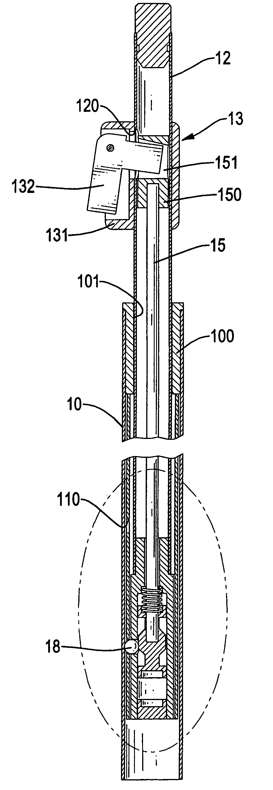
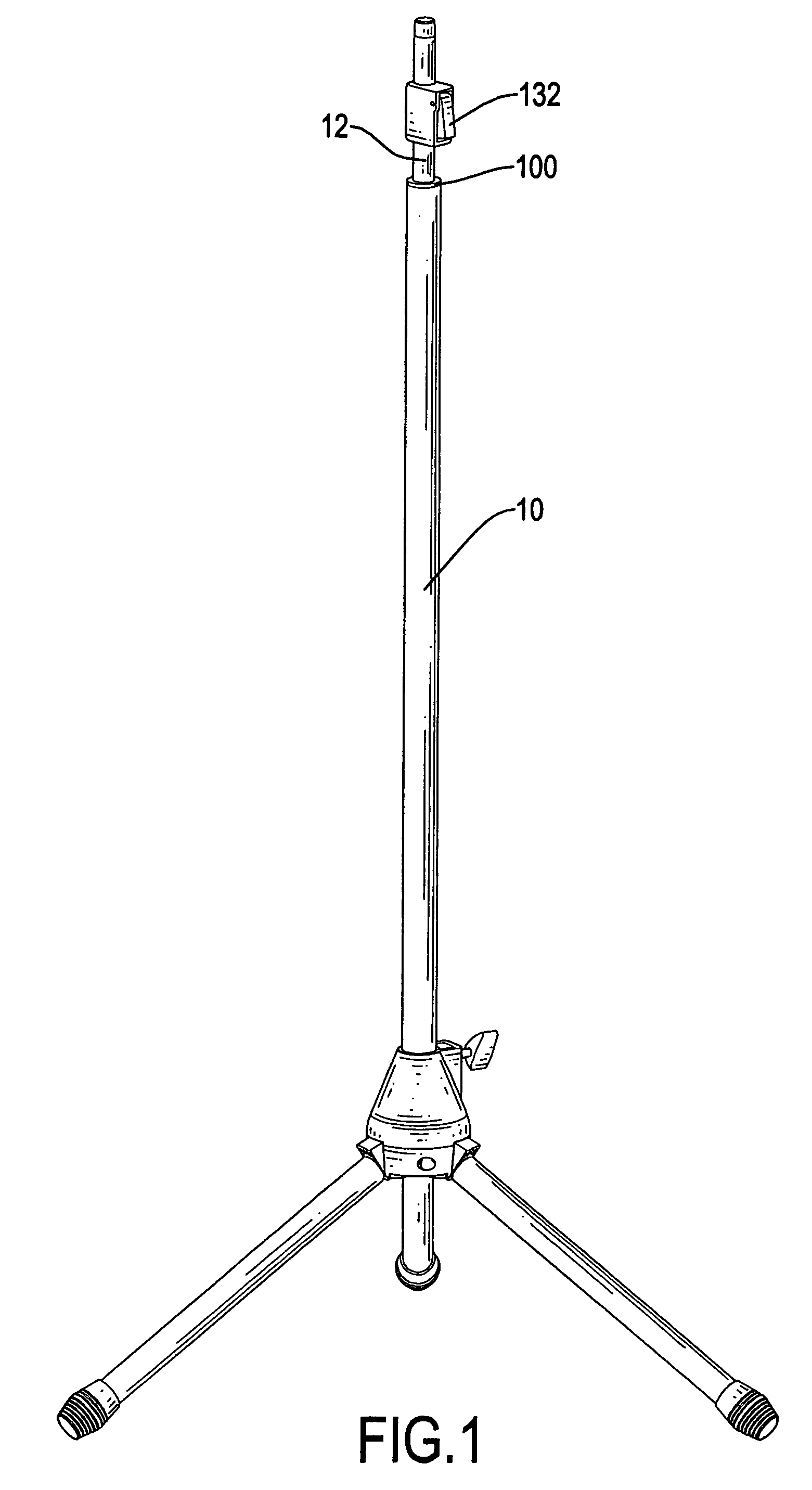
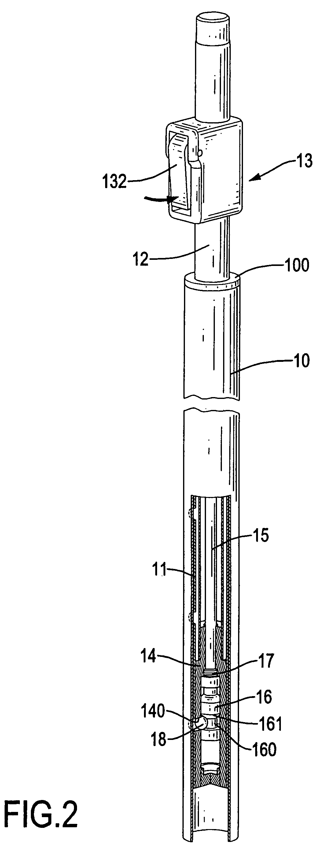
[0026]With reference to FIGS. 1 and 2, a quick-acting telescopic tube in accordance with the present invention comprises a stationary tube (10), a detent lining (11), an extension tube (12), an lock activating assembly (13), a bottom plug (14), an activating rod (15), a spring (17) and a ball (18).

[0027]With further reference to FIG. 3, the stationary tube (10) has a top, a bottom and a bushing (100). The bushing (100) is mounted in the top of the stationary tube (10) and has a through hole (101). The through hole (101) is formed coaxially through the bushing (100).

[0028]The detent lining (11) is mounted securely in the stationary tube (10) and has a top, a sidewall and multiple detents (110). The detents (110) are formed separately in the sidewall of the detent lining (11) and may be annular grooves, annular slots, through holes or the like.

[0029]The extension tube (12) is mounted movably in the detent lining (11) and the stationary tube (10), extends through the through hole (101)...


PUM


Abstract

A quick-acting telescopic tube has a stationary tube, a detent lining, an extension tube, a lock activating assembly, a bottom plug, an activating rod, a spring and a ball. The detent lining is mounted securely in the stationary tube and has multiple detents. The extension tube is mounted movably in the detent lining and has a top and a bottom. The lock activating assembly is mounted around the top of the extension tube and has a lever extending into the extension tube. The bottom plug is mounted securely in the bottom of the extension tube and has a transverse through hole. The activating rod is mounted in the extension tube, connects to the lever and has a locking piston with an annular recess. The ball is mounted in the transverse through hole and selectively in either one of the detents or the annular recess.

Description

BACKGROUND OF THE INVENTION[0001]1. Field of the Invention[0002]The present invention relates to a telescopic tube, especially to a quick-acting telescopic tube that can support a musical instrument.[0003]2. Description of the Prior Arts[0004]With reference to FIG. 6, a conventional telescopic tube comprises a tube assembly (60), a lock activating assembly (70) and a locking assembly (80).[0005]The tube assembly (60) comprises a stationary tube (61), a plug (62), a locking rod (63), an extension tube (64) and an activating tube (65).[0006]The stationary tube (61) has a bottom. The plug (62) is mounted in the bottom of the stationary tube (61). The locking rod (63) is mounted in the stationary tube (61), is attached to the plug (62) and has multiple locking notches (631). The locking notches (631) are formed separately in the locking rod (63).[0007]With further reference to FIG. 7, the extension tube (64) is mounted slidably in the stationary tube (61) and has a top end, a bottom end...

Claims


Application Information

Patent Timeline
Patent Type & Authority Patents(United States)
IPC IPC(8): F16M11/00F16B7/10
CPCF16B7/105F16M11/28F16M11/242Y10T403/32426F16M2200/027F16M2200/028
Inventor HSIEH, WU-HONG
Owner K H S MUSICAL INSTR CO LTD
Why Eureka
Try Eureka