Fixing clamp for anchoring a component in the hole of a support plate

Inactive Publication Date: 2007-04-17
A RAYMOND & CO
View PDF16 Cites 11 Cited by
  • Summary
  • Abstract
  • Description
  • Claims
  • Application Information

AI Technical Summary

Problems solved by technology

Known fixing clamps are poorly suited for preassembly, because they are designed only for direct fixing in the hole of a metal plate, but not for a preassembly in the hole of the molded ceiling, which is made from a less rigid materi

Method used


Image

  • Fixing clamp for anchoring a component in the hole of a support plate
  • Fixing clamp for anchoring a component in the hole of a support plate
  • Fixing clamp for anchoring a component in the hole of a support plate

Examples


Embodiment Construction

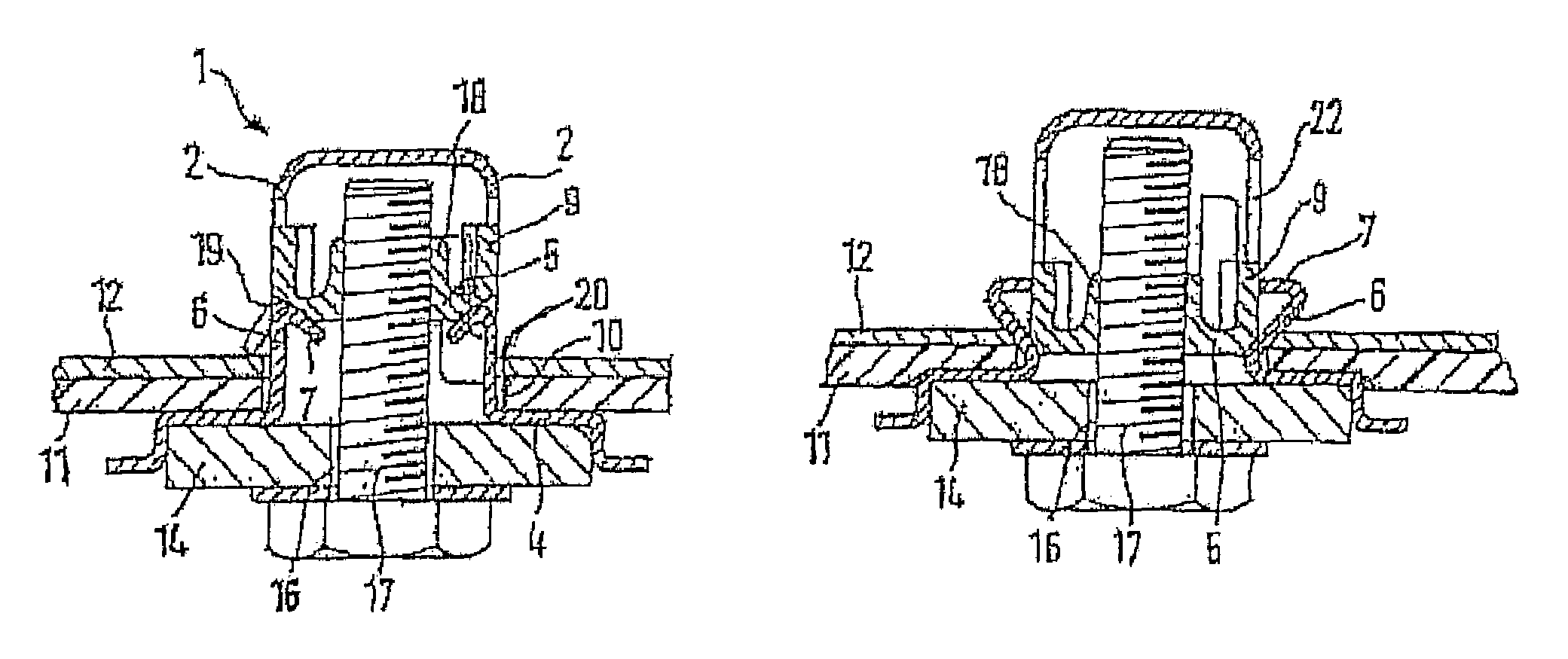
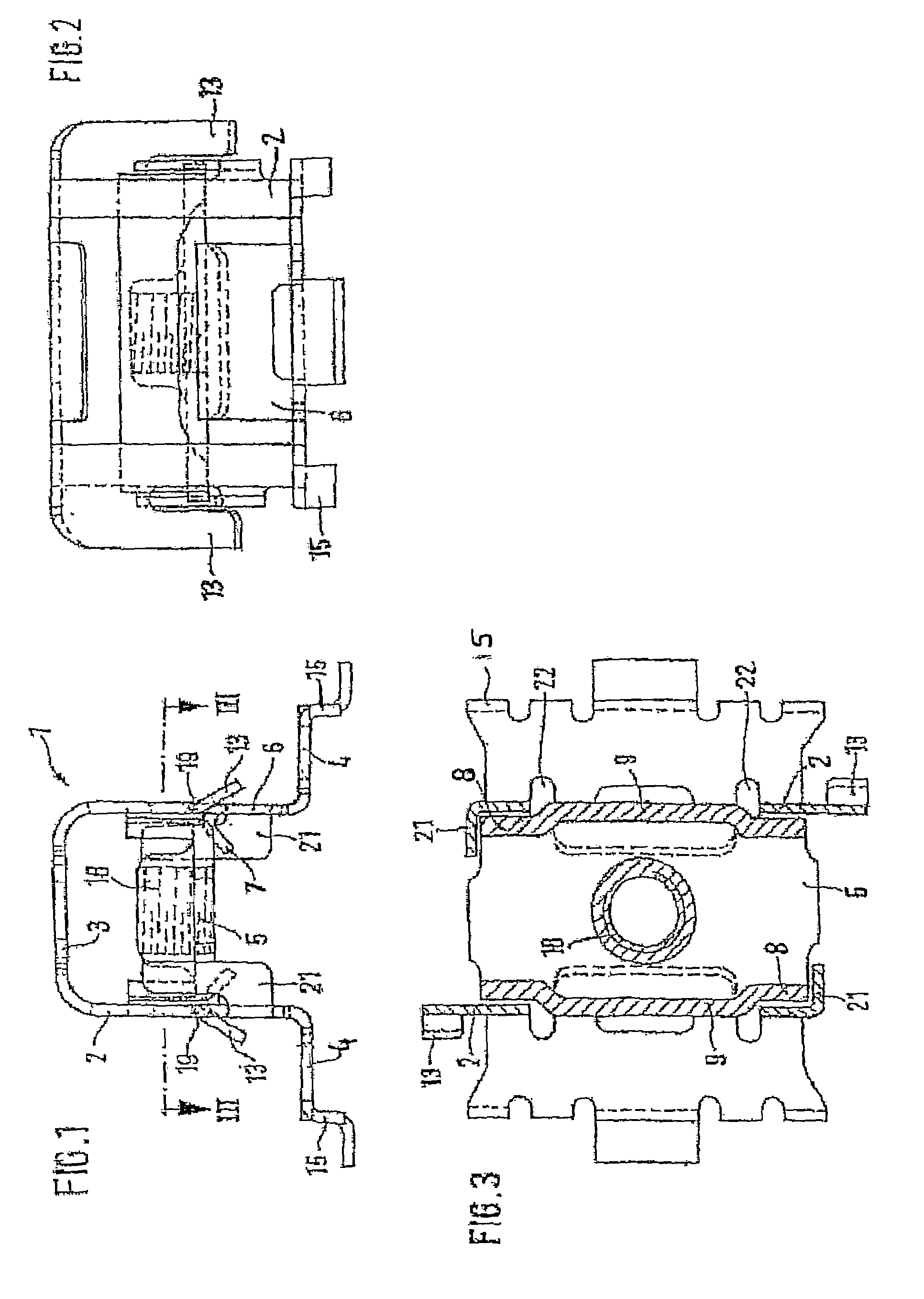
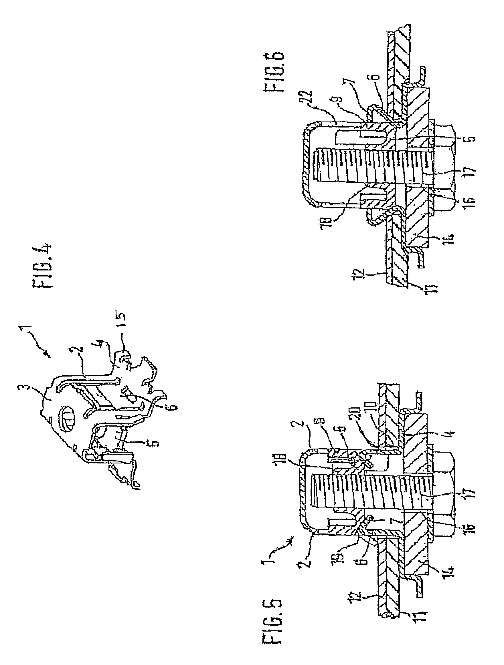
[0015]Referring to FIGS. 1–6, a fixing clamp is illustrated for anchoring a component within an aperture in a support plate 12. The clamp includes a generally U-shaped anchoring part 1. The anchoring part 1 includes two spaced apart side walls 2 each having upper and lower ends. Each side wall 2 extends longitudinally between opposite ends. An upper transverse wall 3 extends between the upper ends of the side walls 2. A locating strip 4 projects outwardly at generally right angles from each lower end of each side wall 2. A transitional corner is defined by the intersection between each locating strip 4 and each respective side wall 2. A transverse tab 21 is bent inwardly from at least one end of each side wall 2. Further, the transverse tabs 21 are disposed at opposite ends of the respective side walls 2. As described in further detail below, a threaded plate 5 is disposed between the side walls 2, such that opposite corners of the threaded plate 5 are movably guided by the transver...


PUM


Abstract

A fixing clamp for anchoring a component within a hole in a support plate includes an anchoring part having two side walls and a transverse wall, a generally planar locating strip projecting outwardly, an expanding tab projecting upwardly that defines a window in the side wall, and an inwardly bent edge strip on an end of the expanding tab. The fixing clamp also includes a movable threaded plate initially supported by the edge strip. The fixing clamp further includes a holding plate for the component and a fixing screw, and the fixing screw is threaded onto the threaded casing of the threaded plate, such that tightening of the fixing screw displaces the threaded plate downwardly along a longitudinal axis of the threaded portion of the fixing screw while deforming the expanding tabs outwardly until the expanding tabs are clampingly engaged with the support plate.

Description

BACKGROUND OF THE INVENTION[0001]1. Field of the Invention[0002]The invention relates to a fixing clamp for anchoring a component in a hole in a support plate, especially for the blind fixing of a handle to the ceiling of a motor vehicle.[0003]2. Description of the Related Art[0004]Fixing clamps are known for anchoring a component in a hole in a support plate. They usually include an anchoring part with locating strips projecting outward at right angles as well as expanding tabs that are connected to a threaded plate. The expanding tabs are located opposite each other and spread outward by screwing a screw supported on the component into the threaded plate, such that the expanding tabs are supported on the back side of the edge of the hole in the support plate. An example of a fixing clamp is disclosed in U.S. Pat. No. 2,184,783.[0005]It is desirable that during the blind fixing of a handle to the ceiling of a motor vehicle, that the handle be at first preassembled with the fixing c...

Claims


Application Information

Patent Timeline
IPC IPC(8): F16B39/284F16B5/06F16BF16B2/20F16B13/06F16B37/04
CPCF16B37/067F16B5/02Y10S411/97
Inventor HULLMAN, KLAUSDE JONG, MICHAELHABROM, MARTINKARG, HORSTMAAS, ASCHWIN
Owner A RAYMOND & CO
Why Eureka
Try Eureka