Alignable coupling assembly for connecting two prosthetic limb components

Inactive Publication Date: 2017-02-02
LIM INNOVATIONS
View PDF1 Cites 13 Cited by
  • Summary
  • Abstract
  • Description
  • Claims
  • Application Information

AI Technical Summary

Benefits of technology

[0043]Accordingly, a method of aligning a distal prosthetic component with respect to a proximal prosthetic component includes coupling the distal and proximal prosthetic components together, and then tightening the bolts. Suc

Problems solved by technology

If the prosthetic socket does not fit properly, it can be uncomfortable for the patient, even to a level of intolerability.
If the fit is poor, even to a minor degree, functionality of the distal prosthetic component is compromised.
If alignment is wrong, the prosthetic socket can become uncomfortable when worn, even if it ostensibly fits well.
And similarly, if alignment between the prosthetic soc

Method used


Image

  • Alignable coupling assembly for connecting two prosthetic limb components
  • Alignable coupling assembly for connecting two prosthetic limb components
  • Alignable coupling assembly for connecting two prosthetic limb components

Examples


embodiment 10

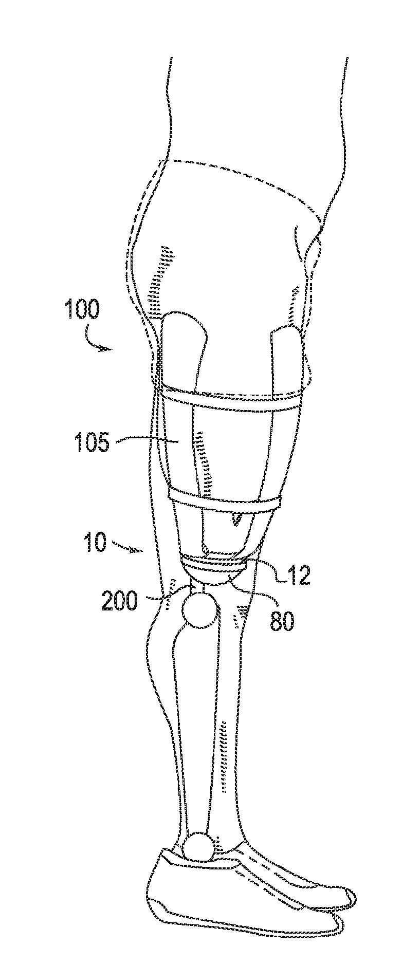
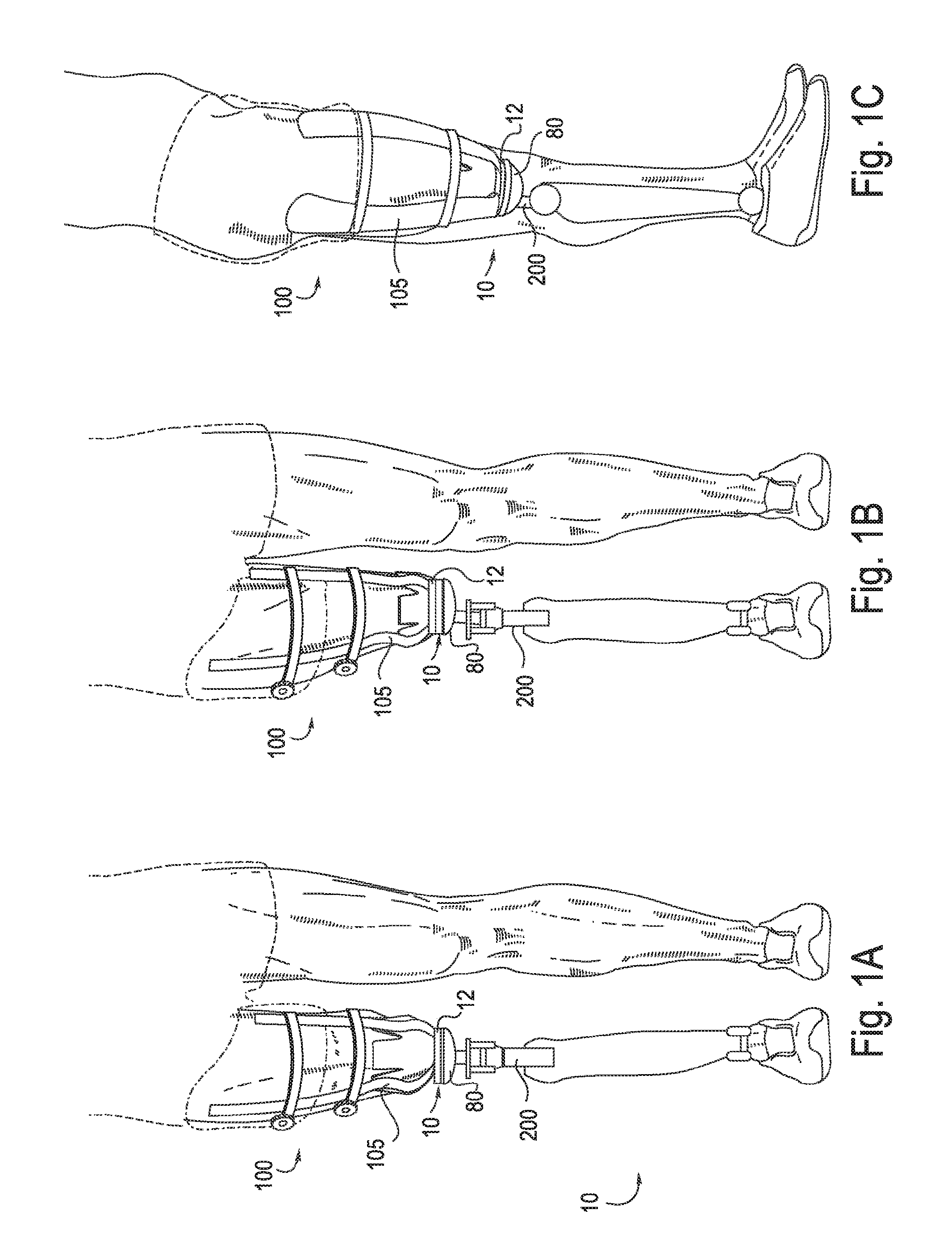
[0089]FIG. 1B is a front view of an embodiment of a modular prosthetic socket 100 with the alignable coupling assembly 10 adjusted so the longitudinal axis of the distal prosthetic component 200 is shifted in a lateral direction with respect to the longitudinal axis of the prosthetic socket. FIG. 1C shows a side view of the modular prosthetic socket 100 with the alignable coupling assembly embodiment 10 adjusted so the longitudinal axis of the distal prosthetic component 200 is shifted in a posterior direction with respect to the longitudinal axis of the prosthetic socket. Each of these shifts or adjustments in the position of the distal component with respect to the proximal prosthetic component is a common type of positional shift that makes biomechanical sense for a patient, and each type of shift is enabled by embodiments of an alignable coupling assembly, as provided herein.

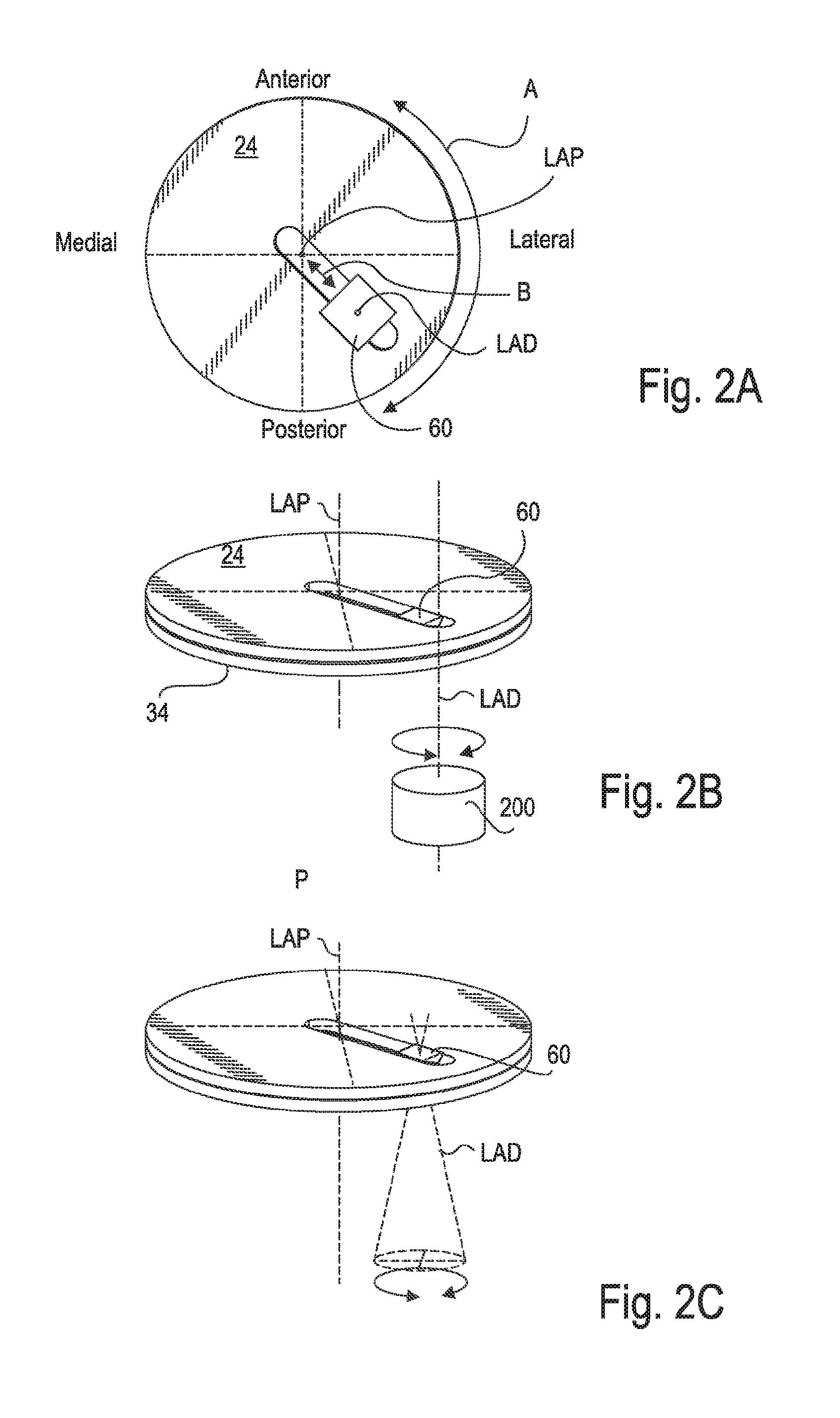
[0090]FIGS. 2A-2C are schematic representations of various aligning or positioning capabilities provided ...

embodiment 160

[0104]The second rotational option takes advantage of an embodiment of the alignable coupling assembly in which an alternative longitudinal connector embodiment 160 has a 2-part arrangement that includes a proximal slider portion that has a circular receptacle that rotatably houses a distally projecting distal portion of longitudinal connector. This rotational capability is shown in FIG. 10C, wherein the distal connecting feature 66 of longitudinal connector 60 is seen in a position that is rotated with respect it its position shown in FIG. 10B.

[0105]Rotation of circular plates 24 and 34 within circular receptacle 52 of support plate 50 actually provides a third rotational option. Rotation of the circular plates 24 and 34 within circular receptacle 52 rotates longitudinal connector 60 that is hosted within slot 40. The axial center of rotation is, unlike the first and second options above, the longitudinal axis of the proximal prosthetic component; nevertheless, a rotation of the pl...


PUM


Abstract

An alignable coupling assembly embodiment for coupling distal and proximal prosthetic components includes a pair of parallel circular plates rotatably disposed in the circular receptacle of a support plate. The circular plates are configured such that they can be unpressed or a pressed. The unpressed condition allows rotation of the paired plates and the pressed condition prevents such rotation by way of a first friction lock. The paired circular plates further have a rectangular slot into which a longitudinal connector is slidably disposed, and which is subject to a second friction lock that prevents sliding when the connector is pulled distally. Rotational movement of the plates and sliding movement of the connector in the slot cooperate to allow its positioning at any point within an anterior-posterior/lateral medial grid centered on the longitudinal axis of the proximal prosthetic component. A distal pull on the longitudinal connector engages both first and second friction locks.

Description

CROSS-REFERENCE TO RELATED APPLICATIONS[0001]This application is a continuation of U.S. patent application Ser. No. 14 / 703,481 entitled “ALIGNABLE COUPLING ASSEMBLY FOR CONNECTING TWO PROSTHETIC LIMB COMPONENTS,” filed May 4, 2015, which claims priority to U.S. Provisional Patent Application No. 61 / 988,824, filed May 5, 2014. The full disclosures of the above-listed patent applications are hereby incorporated by reference for all purposes.INCORPORATION BY REFERENCE[0002]All publications and patent applications mentioned in this specification are herein incorporated by reference to the same extent as if each such individual publication or patent application were specifically and individually indicated to be so incorporated by reference.TECHNICAL FIELD[0003]The technology relates to an alignable coupling assembly to connect two structural elements together to provide stabilizable, rotational capability and alignment adjustment of one structural element with respect to the other. More ...

Claims


Application Information

Patent Timeline
IPC IPC(8): A61F2/76A61F2/64
CPCA61F2/76A61F2/64A61F2002/608A61F2002/5016A61F2002/607A61F2002/6854A61F2002/5018A61F2002/5023
Inventor WILLIAMS, JESSE ROBERTHURLEY, GARRETT RAY
Owner LIM INNOVATIONS
Why Eureka
Try Eureka