Multi-beam pitch adjusting apparatus and image forming apparatus

a multi-beam pitch and adjustment apparatus technology, applied in the field can solve the problems of affecting the accuracy of multi-beam light source apparatus, affecting the accuracy of multi-beam scanning apparatus,

Inactive Publication Date: 2007-04-17
RICOH KK
View PDF19 Cites 17 Cited by
  • Summary
  • Abstract
  • Description
  • Claims
  • Application Information

AI Technical Summary

Problems solved by technology

However, when the former device is applied to, there arises a problem that another beam property (e.g. a beam spot radius) possibly deteriorates.
In addition, due to a limit of physical arrangement, the latter device can probably not be applied to the above-described multi-beam light source apparatus.
Further, when a method of combining a plurality of laser beams with a beam combining device is utilized, a change in a beam pitch or scanning line interval on a scan receiving surface frequently arises as a problem along a change in e

Method used


Image

  • Multi-beam pitch adjusting apparatus and image forming apparatus
  • Multi-beam pitch adjusting apparatus and image forming apparatus
  • Multi-beam pitch adjusting apparatus and image forming apparatus

Examples


Embodiment Construction

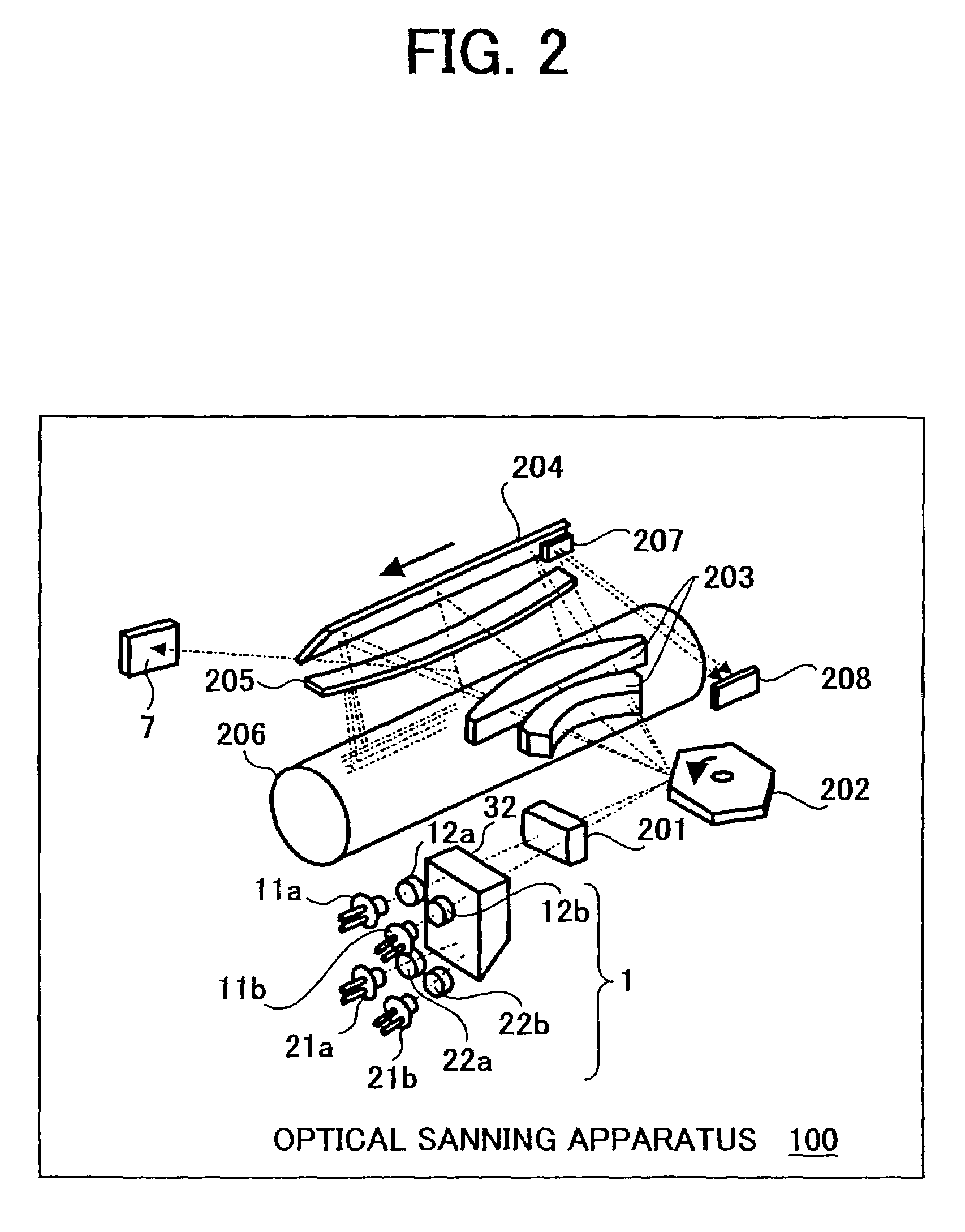
[0051]Referring now to the drawings, wherein like reference numerals and marks designate identical or corresponding parts throughout several views, FIG. 2 is a perspective view illustrating a schematic configuration of an optical scanning apparatus 100 disposed in a color laser printer serving as an exemplary image forming apparatus. As shown, the optical scanning apparatus 100 includes a light source apparatus 1, a cylindrical lens 201, a polygon mirror 202, an Fθ lens 203, a reflection mirror 204, a correction use lens 205, a photo-conductive drum 206, a mirror 207, and a sensor baseboard 208. The optical scanning apparatus 100 irradiates four laser beams from the light source apparatus 1, and enables the cylindrical lens 201 to fair respective laser beams to those having small radiuses and prescribed shapes of lateral cross sections. Then, such faired laser beams are irradiated to the polygon mirror 202 rotating in a prescribed rotational speed, and so that respective laser beams...


PUM


Abstract

A multi-beam scanning apparatus includes a light source having first and second light source sections that hold a pair of semi-conductor laser diodes and coupling lenses that couple four beams irradiated from the pair of semi-conductor laser diodes with a base member. A light beam deviating device may be provided so as to deviate the four beams. A scan imaging device is also provided so as to scan a scan receiving surface with beam spots of the beams deviated by the light beam deviating device. A beam pitch-detecting device is also provided so as to detect a beam pitch of the respective beams formed on the scan-receiving surface. A beam pitch correcting device is provided in order to correct the beam pitch by causing relative deviation of a light axis among the respective beams on a sub scanning direction cross sectional plane.

Description

CROSS REFERENCE TO RELATED APPLICATIONS[0001]This application claims priority under 35 USC §119 to Japanese Patent Application Nos. 2001-223363 and 2001-315011 filed on Jul. 24, and Oct. 12, both 2001, the entire contents of which are herein incorporated by reference.BACKGROUND OF THE INVENTION[0002]1. Field of the Invention[0003]The present invention generally relates to a multi-beam scanning apparatus that simultaneously outputs a plurality of beams, and an image forming apparatus that writes an image with a multi-beam, and more particularly to a technology capable of detecting and correcting a beam pitch on a scan receiving surface in accordance with a detection result.[0004]2. Discussion of the Background[0005]Among various image forming apparatuses using an electro-photographic system, such as a copier, a printer, a facsimile etc., there is an image forming apparatus capable of enabling a multi-beam light source apparatus to simultaneously irradiate and write a plurality of las...

Claims


Application Information

Patent Timeline
IPC IPC(8): B41J15/14B41J27/00B41J2/47G02B26/12
CPCB41J2/473G02B26/123
Inventor AMADA, TAKUSHIMADA, KAZUYUKI
Owner RICOH KK
Why Eureka
Try Eureka