Automated knowledge system for equipment repair based on component failure history

a technology of automatic knowledge system and component failure history, applied in the direction of instruments, nuclear elements, nuclear engineering, etc., can solve the problems of equipment failure in a factory frequently not initially diagnosed by repair technicians, maintenance personnel do not, etc., and achieve accurate first time diagnosis of failures

Inactive Publication Date: 2007-04-17
IBM CORP
View PDF16 Cites 49 Cited by
  • Summary
  • Abstract
  • Description
  • Claims
  • Application Information

AI Technical Summary

Benefits of technology

[0009]Therefore, with the invention, historic information and calculated probability of component failure combined with even limited experience on the part of the technician will enable more accurate first time diagnosis of failures. The system provides an opportunity for cross training as technicians reference and learn from repair actions and comments entered by other technicians for past similar problems. This information is invaluable in determining which repair diagnosis and actions were successful and which were not.

Problems solved by technology

This problem can occur when maintenance personnel do not have access to historic information regarding similar or recent failures and repairs.
It can also occur when a repair technician is inexperienced on the tool he or she is trying to repair, or is still in training.
The cause of an equipment failure in a factory is frequently not initially apparent.
Unnecessary replacement of parts results in extended equipment Mean Time To Repair (MTTR) and increased spending on components, some of which are quite expensive.
This process results in additional equipment downtime if a new component is removed and returned to the spare parts inventory and the original part is reinstalled.
An additional concern is that the lack of visibility to effective versus ineffective repairs can result in learning incorrect repair processes.

Method used


Image

  • Automated knowledge system for equipment repair based on component failure history
  • Automated knowledge system for equipment repair based on component failure history
  • Automated knowledge system for equipment repair based on component failure history

Examples


Embodiment Construction

[0014]The present invention and the various features and advantageous details thereof are explained more fully with reference to the nonlimiting embodiments that are illustrated in the accompanying drawings and detailed in the following description. It should be noted that the features illustrated in the drawings are not necessarily drawn to scale. Descriptions of well-known components and processing techniques are omitted so as to not unnecessarily obscure the present invention. The examples used herein are intended merely to facilitate an understanding of ways in which the invention may be practiced and to further enable those of skill in the art to practice the invention. Accordingly, the examples should not be construed as limiting the scope of the invention.

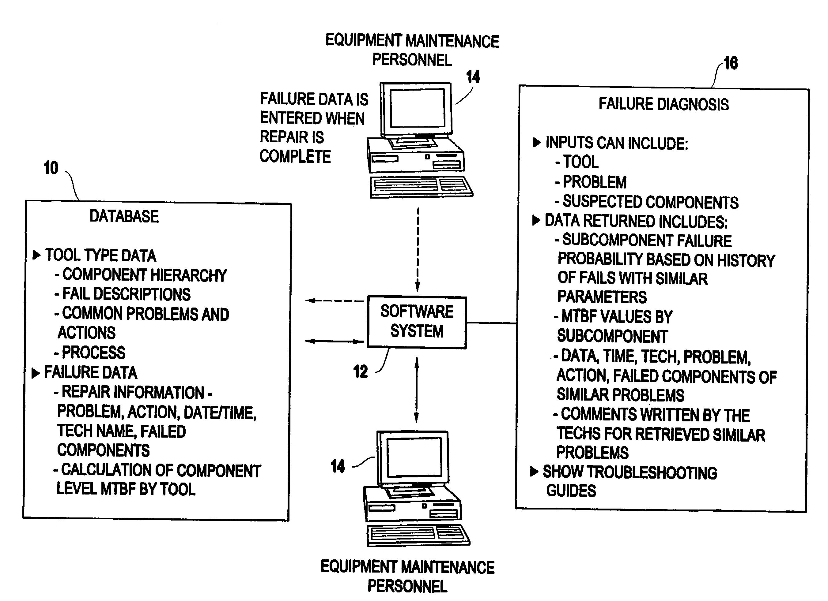
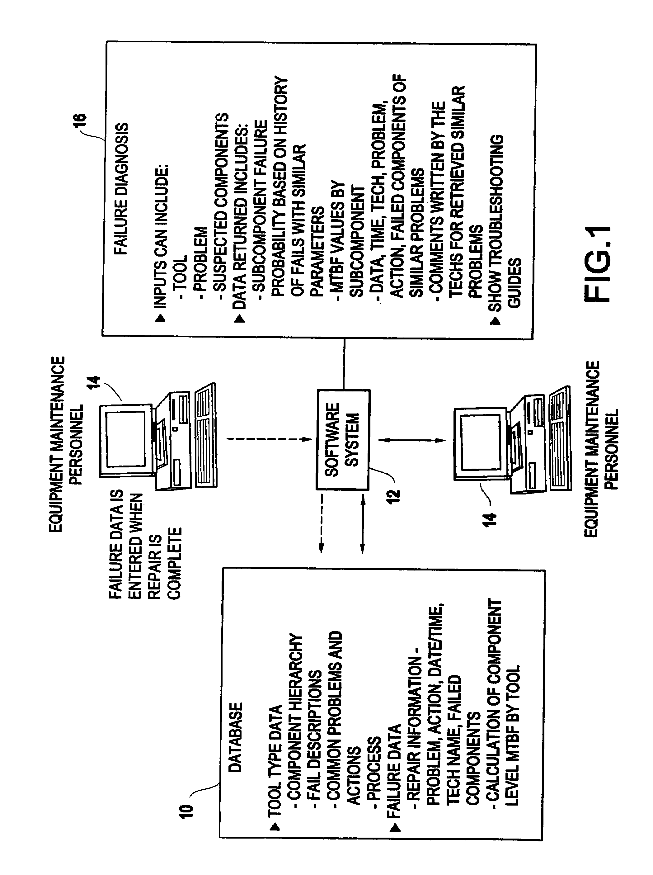
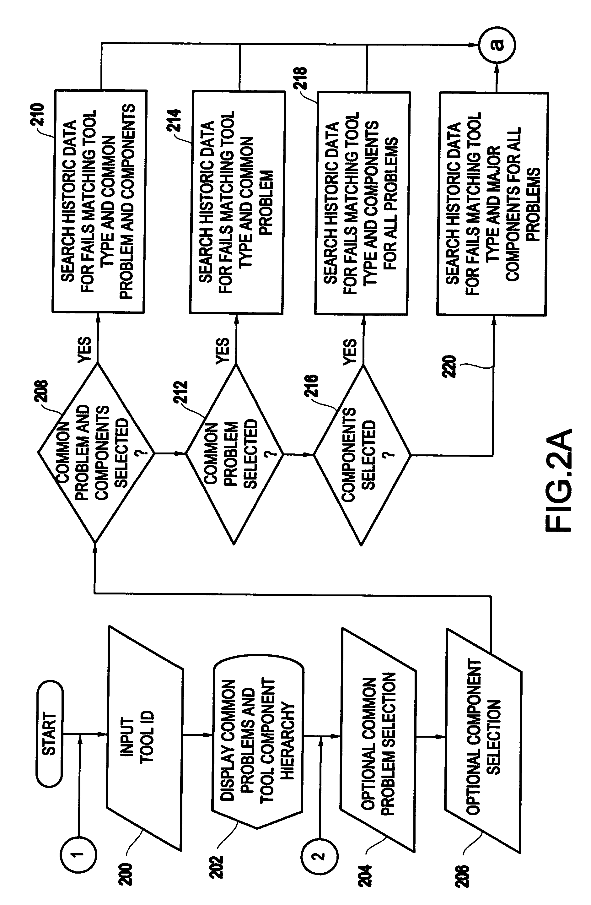
[0015]The invention is a computerized method that uses historic information to predict the likely cause of a current failure. The historic data is gathered when technicians enter information in the system every time a repair...


PUM


Abstract

The invention presents a computerized method for tracking equipment repair that begins by receiving an equipment identification of an item of equipment to be repaired from a user through a graphic user interface. The invention provides the user with a list of common problems for that item of equipment (and similar equipment) and a component hierarchy for the item of equipment. The invention allows the user to browse through multiple levels of the component hierarchy and select a major component, a minor component, or a subcomponent from the component hierarchy. The invention receives diagnosis input from the user optionally selecting one of the problems and / or a component from the component hierarchy and, in response, provides the user with detailed information regarding the problem or component selected by the user. Such detailed information comprises, for each direct subcomponent of the selected component (highest level if none selected), the number of failures, the probability of failure, the mean time between failures, the occurrence of the most recent failure for each component and the next expected failure, etc. Successful prior repairs for the same problem / component are presented including tool, date, time, technician, components involved and action taken. These successful repairs are linked to textual comments regarding the repair. Comments made for what is later determined to be an ineffectual repair are linked to the subsequent successful repair information.

Description

BACKGROUND OF INVENTION[0001]1. Field of the Invention[0002]The present invention generally relates to the problem of excessive repair expense and increased equipment down-time due to inaccurate initial diagnosis of equipment failure.[0003]2. Description of the Related Art[0004]The present invention generally relates to the problem of excessive repair expense and increased equipment downtime due to inaccurate initial diagnosis of equipment failure. This problem can occur when maintenance personnel do not have access to historic information regarding similar or recent failures and repairs. It can also occur when a repair technician is inexperienced on the tool he or she is trying to repair, or is still in training.[0005]The cause of an equipment failure in a factory is frequently not initially apparent. A maintenance technician will make a diagnosis and repair based on their training and experience level. With no access to historic data related to prior repairs, parts may be repaired...

Claims


Application Information

Patent Timeline
Patent Type & Authority Patents(United States)
IPC IPC(8): G06F17/00G01M17/00G06F11/00G06F11/30G06F15/00G06F19/00G06F7/00G06N5/00G21C17/00G06Q10/00
CPCG06Q10/06
Inventor ALVAREZ, BRUCE H.BERGERON, STEVEN R.CAVANAUGH, WILLIAM J.MCCLINTOCK, MICHAEL S.
Owner IBM CORP
Why Eureka
Try Eureka