
Cartridge with locking knife for a curved cutter stapler

a technology of locking knife and stapler, which is applied in the field of cartridge module for surgical stapling and cutting instruments, can solve the problems of inadvertent tissue cut, falling out of staples, bleeding staple lines or worse, etc., and achieve the effect of preventing undesired forward and rearward motion of the kni

Active Publication Date: 2007-04-24
ETHICON ENDO SURGERY INC
View PDF7 Cites 1726 Cited by
  • Summary
  • Abstract
  • Description
  • Claims
  • Application Information

AI Technical Summary

Benefits of technology

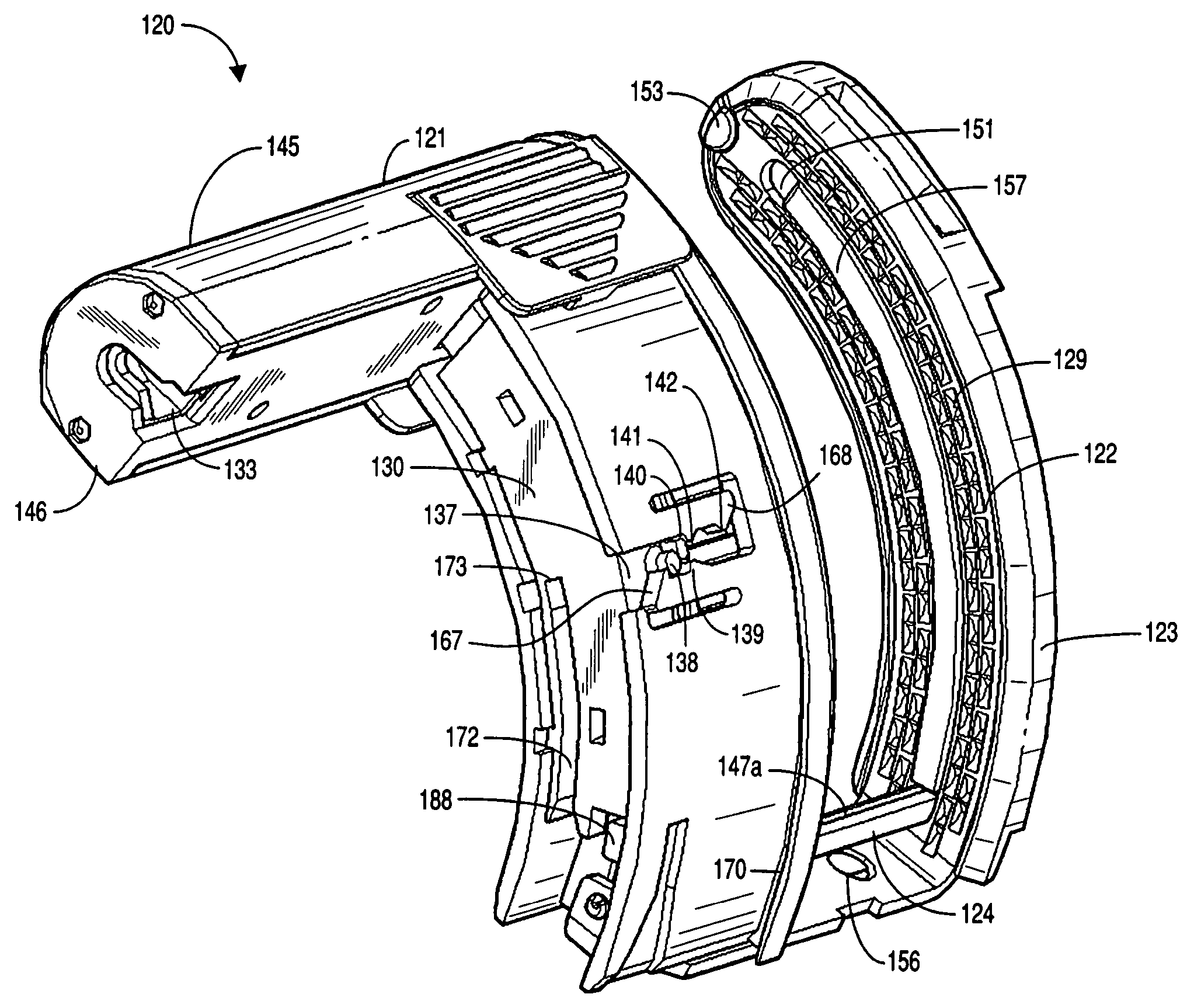
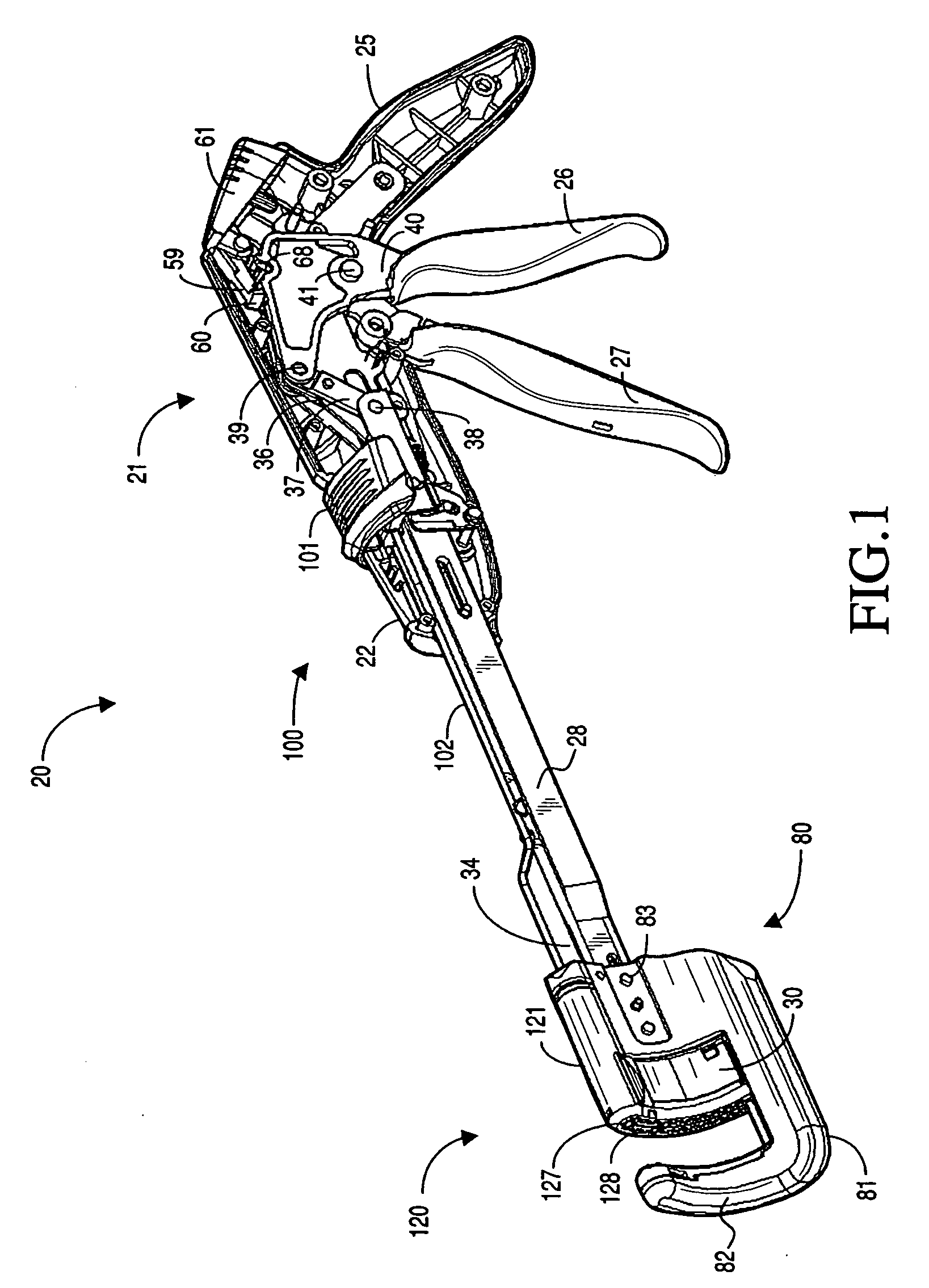
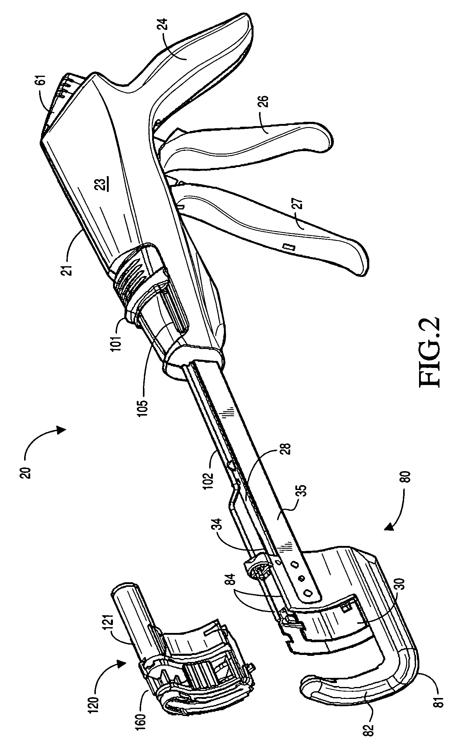
The present invention provides a surgical instrument that can apply multiple surgical fasteners to body tissue. The instrument includes a cartridge module with a driver to push the fasteners out of the cartridge housing. A firing mechanism is associated with the cartridge housing to eject the fasteners and the knife from the cartridge housing. The knife has a detent that prevents unwanted movement. The driver has a detent that contacts the detent of the cartridge module. The cartridge housing has a cartridge slot with flexible fingers that guide the detent of the knife and the driver. The first and second fingers are oriented parallel to the longitudinal axis of the cartridge module. The first finger is shaped and positioned to contact the detent of the knife. The second finger is shaped and positioned to contact the detent of the driver. The cam surfaces are positioned along the edge of each finger and are determined by the desired position of the driver or knife during operation. The technical effects of this invention include improved efficiency and accuracy in surgical procedures and reduced risk of complications.

Problems solved by technology

Movement of the staples out of their pockets may lead to staples falling out or being out of position, both of which may lead to bleeding staple lines or worse.
Movement of the knife assembly to a position where the knife is exposed might cause injury to anyone using the device or an inadvertent cut in tissue during use on a patient.

Method used


Image

  • Cartridge with locking knife for a curved cutter stapler
  • Cartridge with locking knife for a curved cutter stapler
  • Cartridge with locking knife for a curved cutter stapler

Examples


Embodiment Construction

[0041]The detailed embodiment of the present invention is disclosed herein. It should be understood, however, that the disclosed embodiment is merely exemplary of the invention, which may be embodied in various forms. Therefore, the details disclosed herein are not to be interpreted as limiting, but merely as the basis for the claims and as a basis for teaching one skilled in the art how to make and / or use the invention.

[0042]With reference to the various figures, a surgical instrument 20 adapted for applying a plurality of surgical fasteners to body tissue is disclosed. The surgical instrument 20 includes an anvil 122 and a cartridge housing 121 containing a plurality of surgical fasteners and a knife 126. The cartridge housing 121 and anvil 122 are relatively movable between a first spaced apart position and a second position in close approximation with one another. The instrument 20 also includes a firing mechanism associated with the cartridge housing 121 for ejecting the surgic...


PUM

PropertyMeasurementUnit
flexibleaaaaaaaaaa
movementaaaaaaaaaa
forcesaaaaaaaaaa

Abstract

A surgical instrument adapted for applying a plurality of surgical fasteners to body tissue includes a cartridge module having a cartridge housing containing a plurality of surgical fasteners and a knife. The cartridge module includes a driver disposed to push surgical fasteners out of the cartridge housing. The instrument also includes a firing mechanism associated with the cartridge housing for ejecting the surgical fasteners and the knife from the cartridge housing. The knife includes a detent disposed to contact a mating detent of the cartridge module during longitudinal travel of the knife thereby preventing undesired forward and rearward motion of the knife. The driver includes a detent disposed to contact at least one mating detent formed on the cartridge module.

Description

CROSS REFERENCE TO RELATED APPLICATION[0001]This application is based upon U.S. Provisional Patent Application No. 60 / 532,911, filed Dec. 30, 2003, entitled “STAPLER CARTRIDGE FOR A CURVED CUTTER STAPLER”.BACKGROUND OF THE INVENTION[0002]1. Field of the Invention[0003]The present invention relates to a surgical stapling and cutting instrument adapted for use in the diagnosis and therapy of pathologies treated by stapled resection. More particularly, the invention relates to a cartridge module for surgical stapling and cutting instruments that includes detents for the driver and knife assemblies.[0004]2. Description of the Prior Art[0005]Surgical stapling and cutting instruments are commonly utilized in the diagnosis and treatment of pathologies treated by stapled resection. Surgical stapling and cutting instruments provide a mechanism to extend the transluminal exploitation of mechanical suturing devices introduced via the anal canal, mouth, stomach and service accesses. Although su...

Claims


Application Information

Patent Timeline
Patent Type & Authority Patents(United States)
IPC IPC(8): A61B17/04A61B17/11A61B17/3211A61B17/00A61B17/072A61B17/32A61B19/00
CPCA61B17/072A61B17/32A61B2017/0023A61B2017/07214A61B2017/07221A61B2017/07271A61B2017/07285A61B2017/320052A61B2019/308A61B2019/4873A61B2090/038A61B2090/0814
Inventor WUKUSICK, PETER MICHAELSCHWEMBERGER, RICHARD F.
Owner ETHICON ENDO SURGERY INC
Learn More