Patch panel with a motherboard for connecting communication jacks

a technology of communication jacks and patch panels, which is applied in the direction of coupling devices, two-part coupling devices, and contact members penetrating/cutting insulation/cable strands, etc., can solve the problem of not providing reliable documentation in real time, and achieve the effect of enhancing communication network installation, revision, management and documentation

Inactive Publication Date: 2007-04-24
PANDUIT
View PDF195 Cites 129 Cited by
  • Summary
  • Abstract
  • Description
  • Claims
  • Application Information

AI Technical Summary

Problems solved by technology

Prior art systems provide such information, however, they do not provide reliable documentation in real time.

Method used


Image

  • Patch panel with a motherboard for connecting communication jacks
  • Patch panel with a motherboard for connecting communication jacks
  • Patch panel with a motherboard for connecting communication jacks

Examples


Embodiment Construction

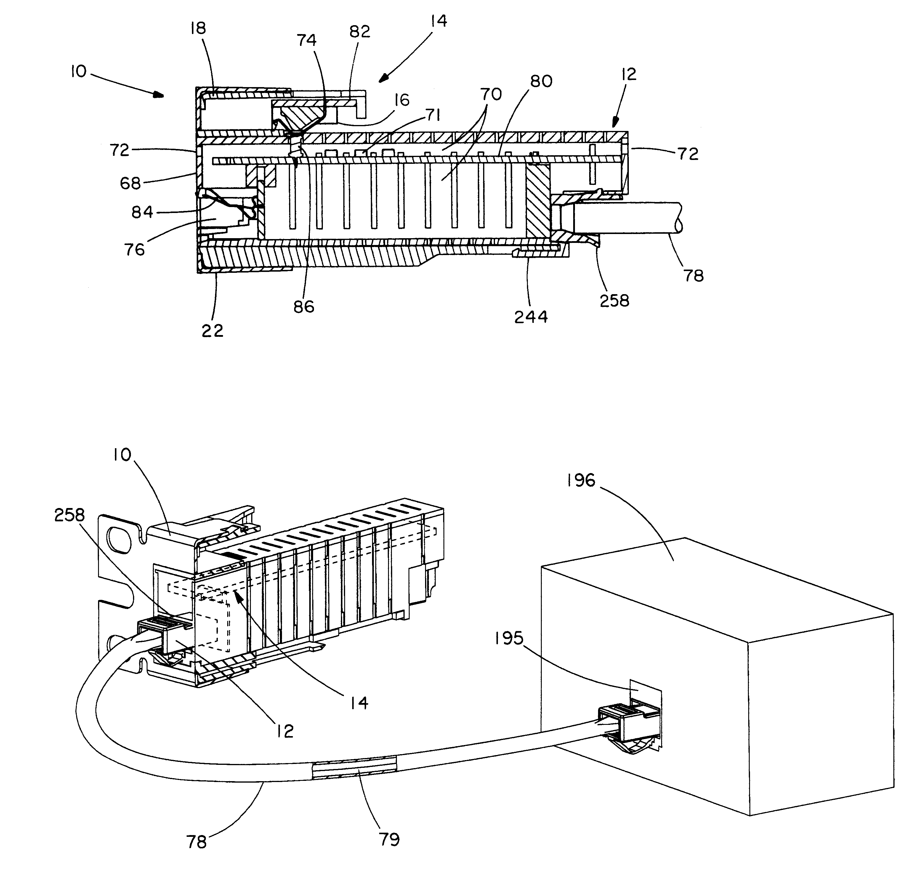
[0063]Active jacks according to the present invention may be considered Ethernet network repeaters that contain media access control (MAC) ID chips and that respond to query signals from a network source with the ID of the jack. They also provide functions required by various standards for PDs. They optionally provide additional functions as described in the above-referenced U.S. patent application Ser. No. 10 / 439,716. When active jacks are installed, their physical locations are recorded in a network system. When a response from a network information query is received on a particular source of a network path (i.e., a particular port of a switch), the system software combines this information with the above-described physical location information and documents network physical structure.

[0064]Active jacks according to the present invention may be provided in several varieties. A standard active jack (“A-Jack”) is the jack to which a destination device (e.g., a voice-over-Internet-pr...


PUM


Abstract

An active jack, which is a powered device, is installed as the network connection at a workstation which provides the capability to determine the physical location of a destination device, such as a VOIP phone, in real time. Uninterruptible power supplies may be used to provide power to network components, for example during an emergency. Power-and-data deployments are shown for powering network components and destination devices.

Description

CROSS-REFERENCE TO RELATED APPLICATION[0001]This application claims the benefit of U.S. Provisional Patent Application Ser. No. 60 / 524,654, filed Nov. 24, 2003 and entitled “Communications Patch Panel Systems and Methods,” U.S. Provisional Patent Application Ser. No. 60 / 529,925, filed Dec. 16, 2003 and entitled “Communications Patch Panel Systems and Methods,” and U.S. Provisional Patent Application Ser. No. 60 / 537,126, filed Jan. 16, 2004 and entitled “Communications Patch Panel Systems and Methods,”.INCORPORATION BY REFERENCE[0002]This application incorporates by reference in its entirety U.S. patent application Ser. No. 10 / 439,716, entitled “Systems and Methods for Managing a Network,” filed on May 16, 2003; U.S. Provisional Application Ser. No. 60 / 492,822, entitled “Network Managed Device Installation and Provisioning Technique,” filed on Aug. 6, 2003; U. S. Provisional Application, entitled “System to Guide and Monitor the Installation and Revision of Network Cabling of an Acti...

Claims


Application Information

Patent Timeline
Patent Type & Authority Patents(United States)
IPC IPC(8): H01R24/00H01R4/24H01R29/00
CPCH01R29/00H01R4/2425H01R24/64
Inventor CAVENEY, JACK E.NORDIN, RONALD A.
Owner PANDUIT
Why Eureka
Try Eureka