
Partition system with elevated raceway

a technology of partition system and raceway, applied in the direction of service system furniture, walls, parkings, etc., can solve the problems of increasing installation and reconfiguration costs, difficult to achieve adequate utility distribution, and complex modern offices

Inactive Publication Date: 2007-05-01
STEELCASE INC
View PDF45 Cites 53 Cited by
  • Summary
  • Abstract
  • Description
  • Claims
  • Application Information

AI Technical Summary

Benefits of technology

[0010]Yet another aspect of the present invention is a partition panel including a generally rectangular partition frame having a base configured to support the partition frame freestanding on a floor surface. The partition frame has a horizontal upper edge. The partition panel also inc

Problems solved by technology

Modern offices are becoming increasingly complicated and sophisticated due largely to the ever increasing needs of the users for improved utilities support at each workstation, such as communications, computers and other types of data processors, electronic displays, etc., including physical accommodations, such as lighting, HVAC, security, and the like.
Both of these types of modular furniture systems, as well as others, have been widely received due largely to their ability to be readily reconfigured and / or moved to a new site, since they are not part of a permanent leasehold improvement.
Since such workstations must be readily reconfigurable to effectively meet the ever changing needs of the user, the distribution and control of utilities throughout a comprehensive open office plan has emerged as a major challenge to the office furniture industry.
While this type of distribution system has proven somewhat effective, the types of utilities provided are rather limited, and their distribution is not wholly modular, thereby resulting in higher installation and reconfiguration costs.
The inherent nature of modular furniture systems, which permits them to be readily reconfigured into different arrangements, makes it very difficult to achieve adequate utility distribution.
Various difficulties may be encountered when routing utility lines through known systems.
However, such arrangements generally add to the complexity and / or cost of the system.
Furthermore, difficulty may be encountered when routing a large volume of wires through such a change of height location.

Method used


Image

  • Partition system with elevated raceway
  • Partition system with elevated raceway
  • Partition system with elevated raceway

Examples


Embodiment Construction

[0025]For purposes of description herein, the terms “upper,”“lower,”“right,”“left,”“rear,”“front,”“vertical,”“horizontal,” and derivatives thereof shall relate to the invention as oriented in FIG. 1. However, it is to be understood that the invention may assume various alternative orientations and step sequences, except where expressly specified to the contrary. It is also to be understood that the specific devices and processes illustrated in the attached drawings and described in the following specification are simply exemplary embodiments of the inventive concepts defined in the appended claims. Hence, specific dimensions and other physical characteristics relating to the embodiments disclosed herein are not to be considered as limiting, unless the claims expressly state otherwise.

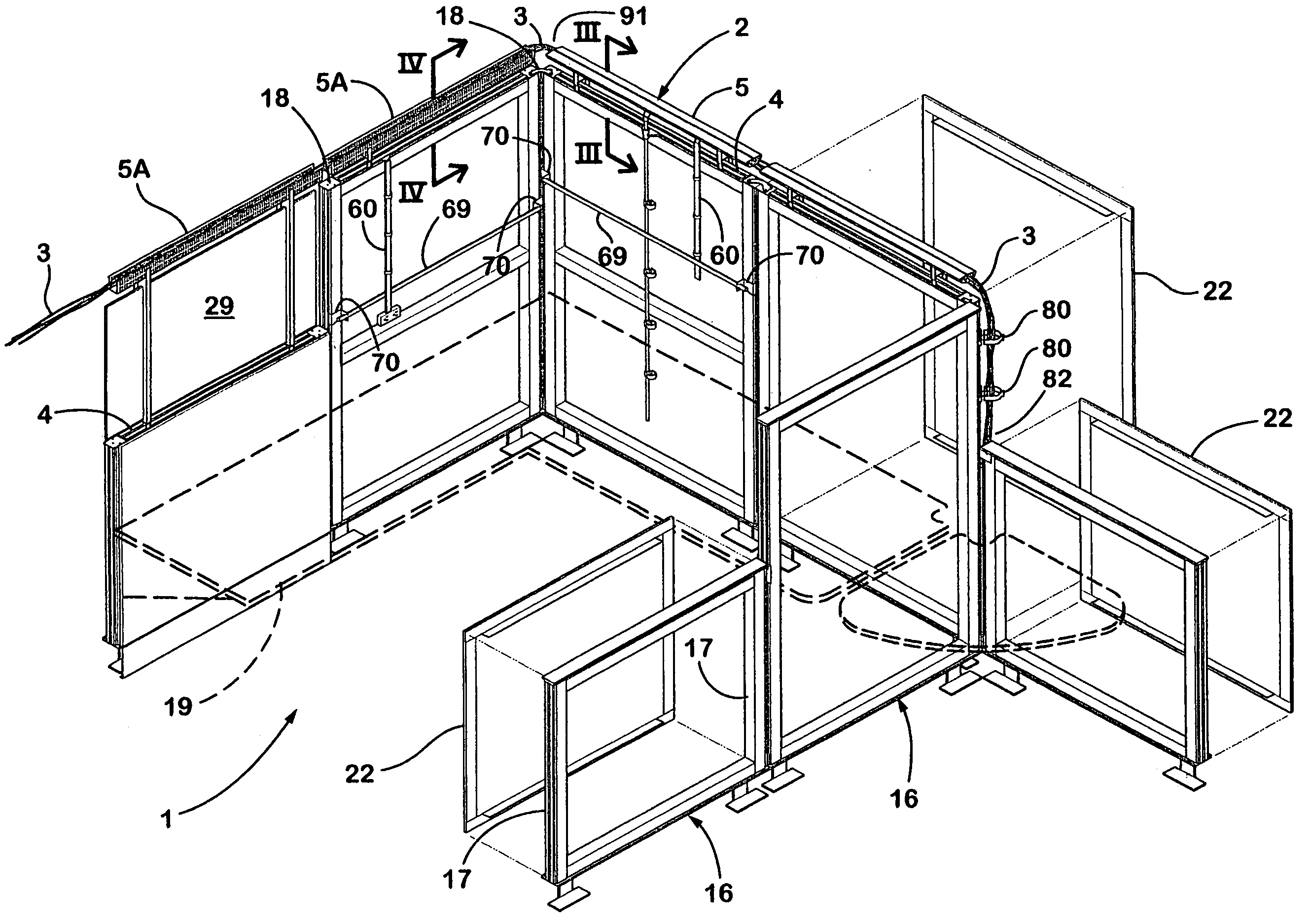
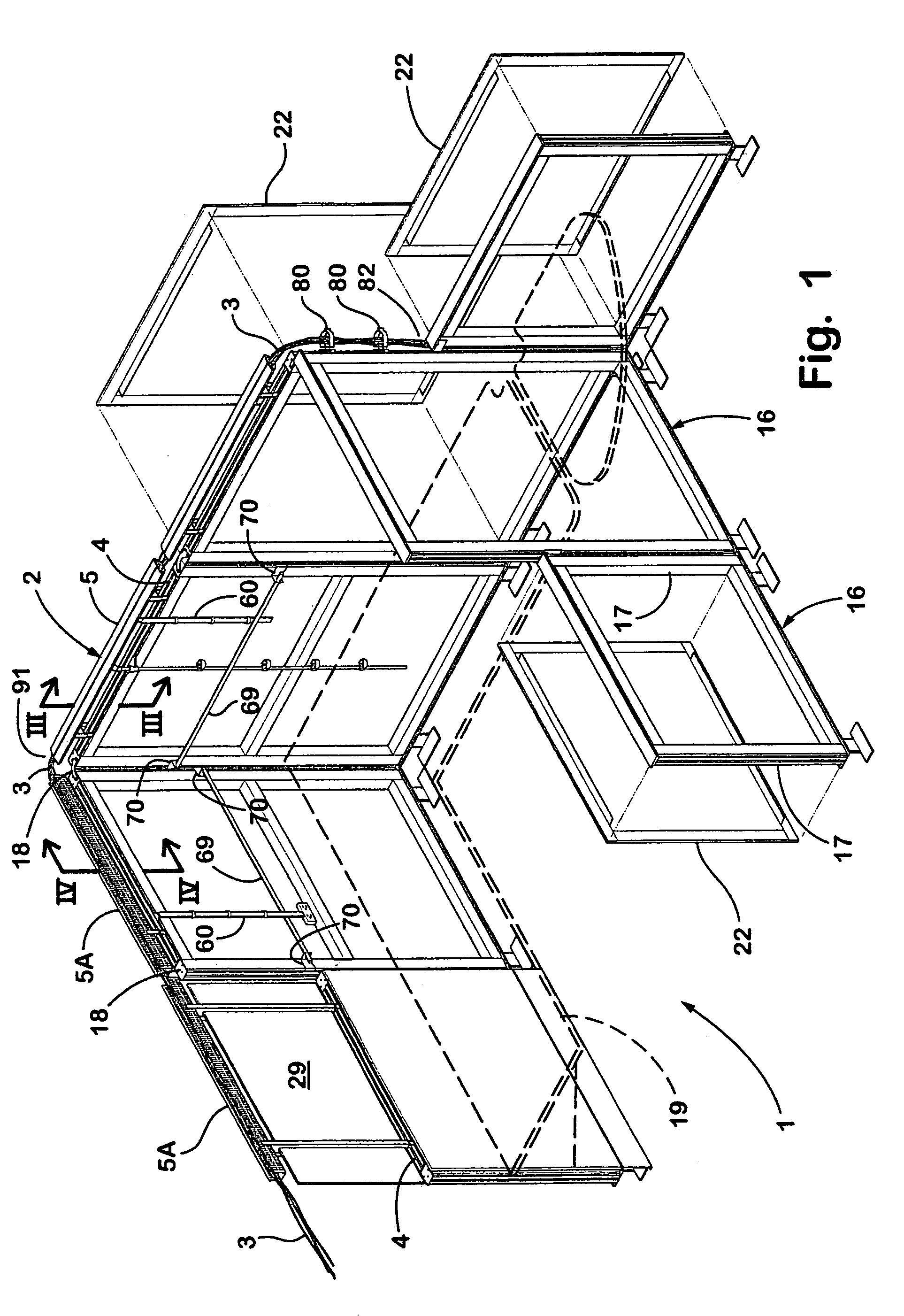
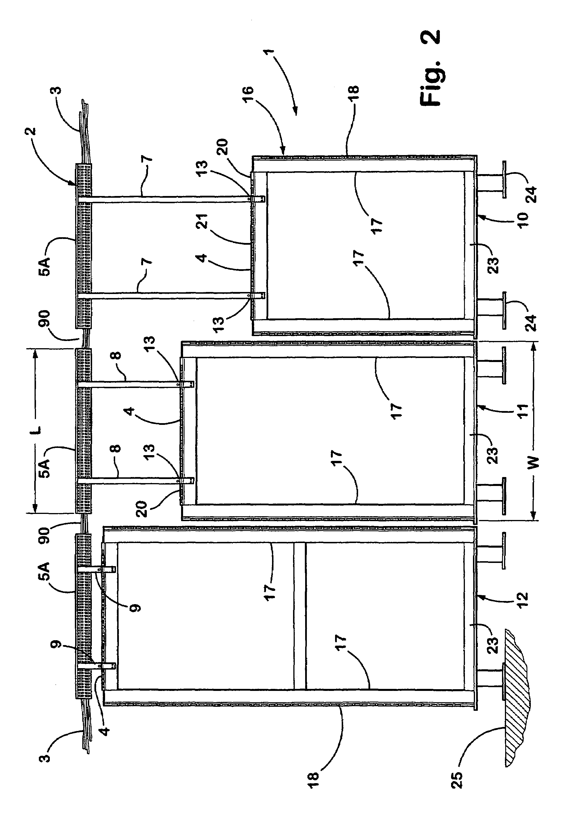
[0026]FIG. 1 illustrates a partition system 1 including an elevated raceway assembly 2 according to the present invention. The elevated raceway assembly 2 routes utility lines 3 such as power or communi...


PUM


Abstract

An elevated raceway for routing utility lines in a vertically spaced relationship above the upper edge of a partition. The raceway includes an elongated passageway configured to retain utility lines in a horizontally extending manner. A first support member extends downwardly from the raceway, and has a connector spaced apart from the raceway a first vertical distance. The connector is configured to attach to a partition frame. A second support member extends downwardly from the raceway, and has a connector spaced apart from the raceway a second vertical distance that is different from the first vertical distance, such that the raceway is supported at a generally uniform vertical height above an upper edge of a partition having sections with different heights.

Description

BACKGROUND OF THE INVENTION[0001]Modern offices are becoming increasingly complicated and sophisticated due largely to the ever increasing needs of the users for improved utilities support at each workstation, such as communications, computers and other types of data processors, electronic displays, etc., including physical accommodations, such as lighting, HVAC, security, and the like. For example, modern offices for highly skilled “knowledge workers” such as engineers, accountants, stock brokers, computer programmers, etc., are typically provided with multiple pieces of very specialized computer and communications equipment that are capable of processing information from numerous local and remote data resources to assist in solving incredibly complex problems. Such equipment has very stringent power and signal requirements, and must quickly and efficiently interface with related equipment at both adjacent and remote locations. Work areas with readily controllable lighting, HVAC, s...

Claims


Application Information

Patent Timeline
IPC IPC(8): E04H1/00E04B2/74H02G3/04H02G3/30
CPCH02G3/0425H02G3/30
Inventor KING, JONATHAN J.RUITER, JOEL T.DEKKER, DAVID J.HOUDA, JAMES D.
Owner STEELCASE INC
Learn More