
Lock for a downhole tool with a reset feature

a technology of reset feature and lock, which is applied in the direction of drilling casings, drilling pipes, and accessories for boreholes/wells, etc., can solve the problems of inability to retain a desired position, increased operating limitations, and ineffective locks

Inactive Publication Date: 2007-05-01
BAKER HUGHES INC
View PDF19 Cites 45 Cited by
  • Summary
  • Abstract
  • Description
  • Claims
  • Application Information

AI Technical Summary

Benefits of technology

The patent describes a lock mechanism for a downhole tool that can hold two parts together temporarily. This mechanism is particularly useful in situations where the movement of the tool is dictated by pressure cycling and a J-slot mechanism. The lock is designed to withstand mechanical impacts and can be easily released to allow for normal tool operation. The technical effect of this invention is to provide a reliable and effective mechanism for holding downhole tools together during use.

Problems solved by technology

One such shortcoming can be the inability to retain a desired position throughout the duration of a particular downhole operation.
In the past, locking the tool in a particular position has been tried, but those attempts created additional operating limitations.
Some locks were effective against pressure variations but were not effective in resisting mechanical impacts.
Since this valve was actuated with pressure cycles in the tubing, it could be affected by pressure spikes in the tubing.
Also, it was susceptible to mechanical impacts on the mandrel that could operate the valve out of the desired position for a specific procedure.
Some operators, particularly in deep water, have high cost completions that need a lock that can be reset to allow injection of fluids through an open valve at high rates without concern that such a procedure will operate the valve out of an open position.
This complex design requires two control lines and due to its complexity was difficult to manufacture economically and was not commercially successful.

Method used


Image

  • Lock for a downhole tool with a reset feature
  • Lock for a downhole tool with a reset feature
  • Lock for a downhole tool with a reset feature

Examples


Embodiment Construction

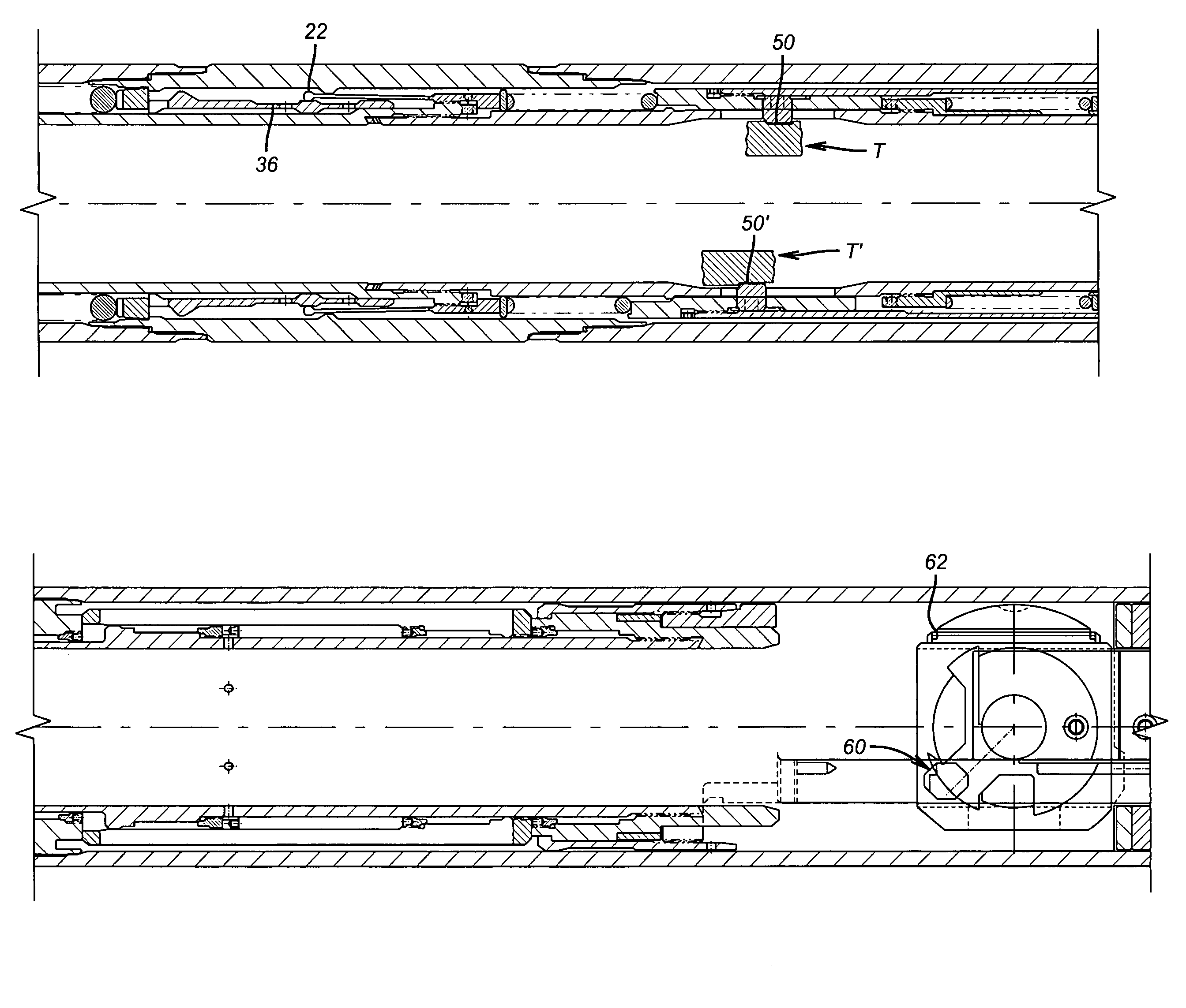
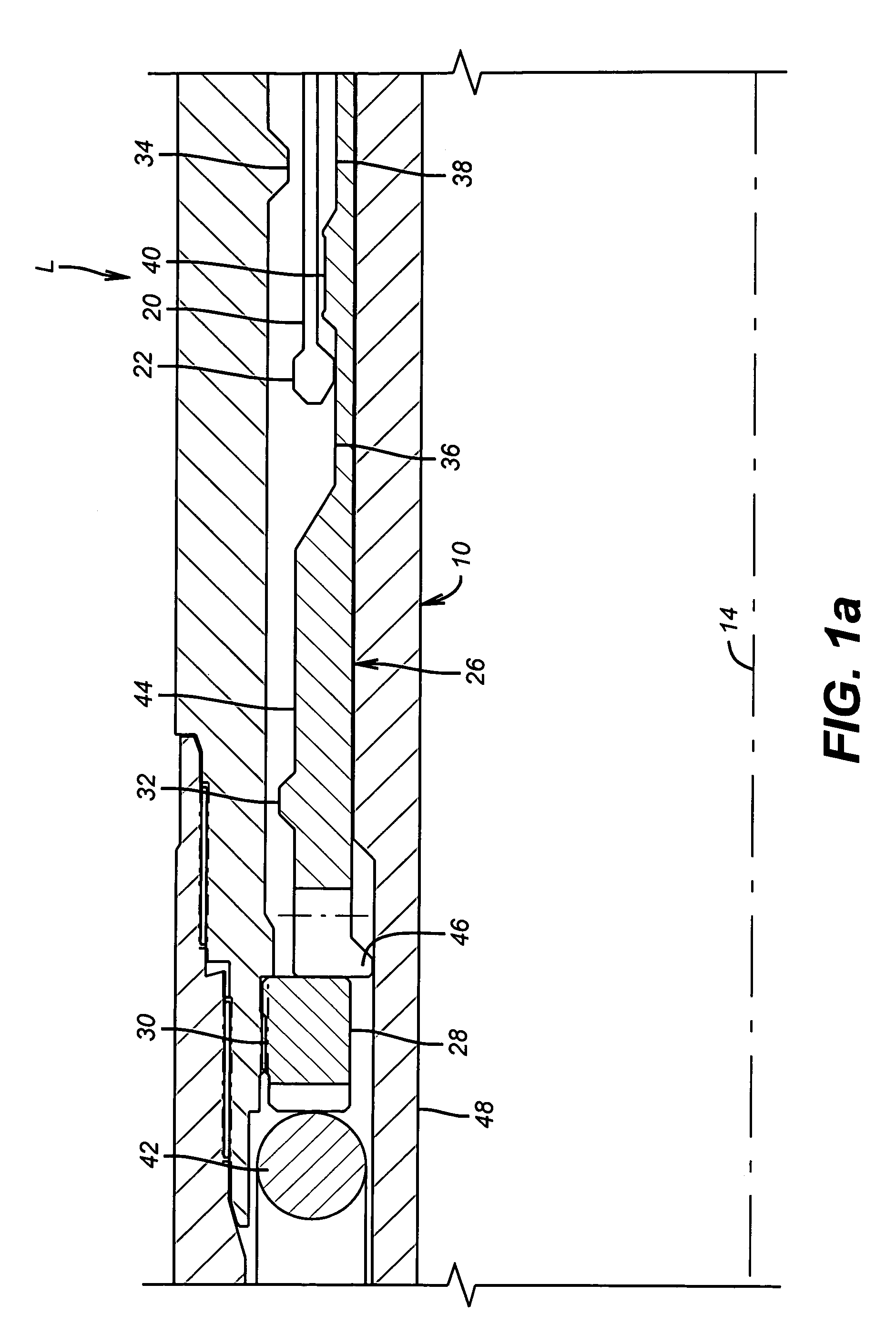
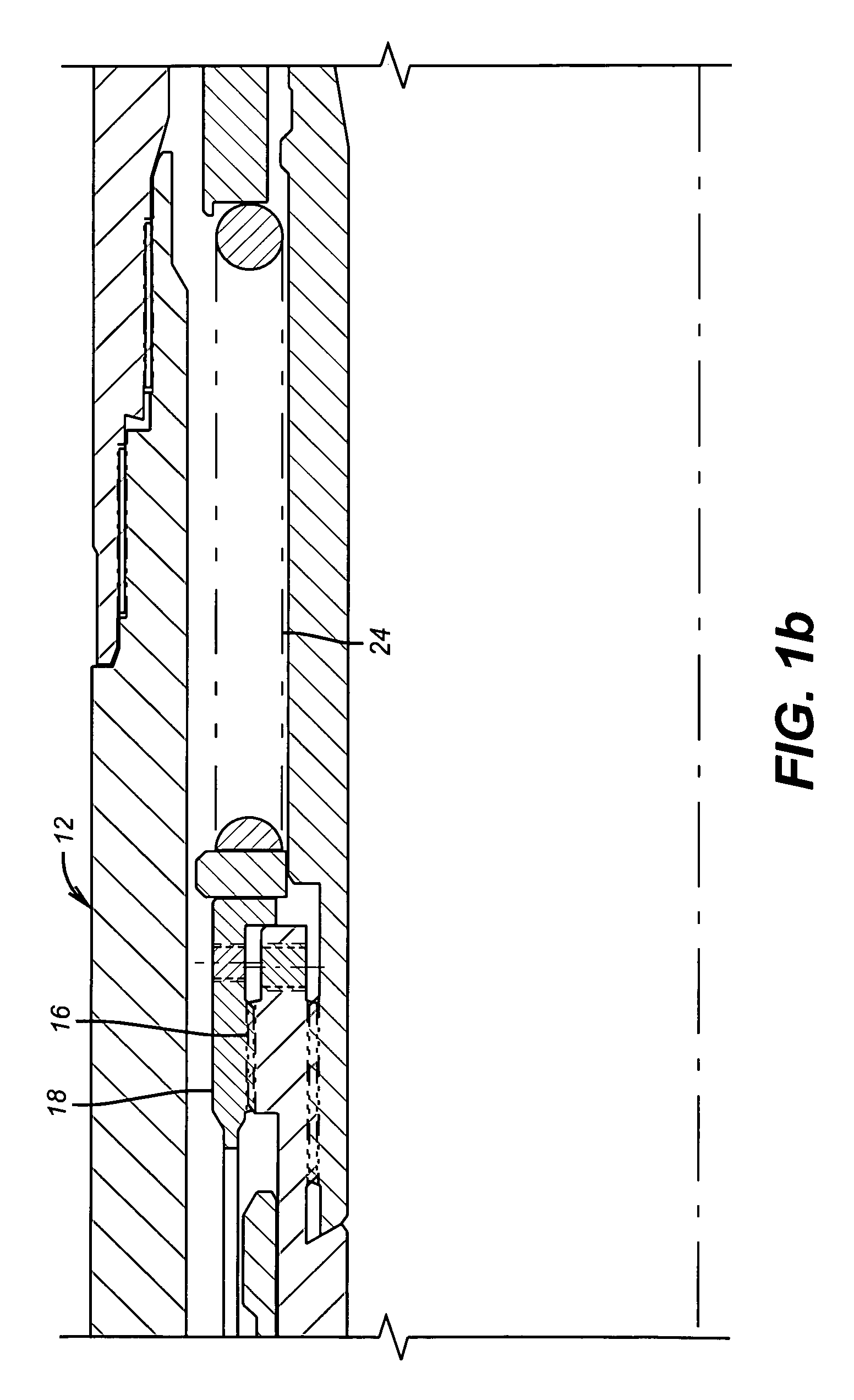
[0016]The drawings illustrate the resetting lock mechanism in detail and omit most of the details of the operation of a tester valve that are known. While an ‘RB’ valve is used for illustrative purposes, the present invention can be deployed in a downhole application where it is desired to hold one member to another during a specific downhole operation and to allow the downhole tool to resume other operations at a later time.

[0017]In the preferred embodiment, the invention is deployed in an ‘RB’ Valve. Such a valve is frequently attached to a packer and employs a j-slot mechanism, which is cycled by virtue of alternating application and removal of pressure downhole. In the preferred embodiment, pressure cycling occurs in the tubing and the pressure cycles, after a predetermined number of cycles, allows a mandrel 10 to shift with respect to a stationary surrounding connector 12 so that the net result can be an alignment or misalignment of ports to selectively open or close the downho...


PUM


Abstract

The lock allows two members in a downhole tool to be temporarily held together. In an application where mandrel movement is dictated by pressure cycling in combination with a J-slot mechanism, such as in a downhole valve, the mandrel is releaseably retained to an adjacent connector against mechanical impacts. The mandrel features an extended collet that moves relatively to a floating sleeve during pressure cycles. At some point the collet heads rise to an elevated groove that causes them to contact a no-go shoulder for locking. The lock is defeated be removing the collet heads from the elevated groove for normal tool operation.

Description

FIELD OF THE INVENTION[0001]The field of the invention is locks for downhole tools that can selectively retain the tool in a position for a particular operation and more particularly locks that can be released and subsequently reset for holding a downhole tool for subsequent operations.BACKGROUND OF THE INVENTION[0002]There are many types of tools used downhole. Some tools are moved repeatedly between positions for the performance of different operations. While these tools are designed to shift between the positions to accomplish downhole functions, the procedures downhole vary with time and tools that readily performed functions in multiple positions reveal a potential shortcoming. One such shortcoming can be the inability to retain a desired position throughout the duration of a particular downhole operation. In the past, locking the tool in a particular position has been tried, but those attempts created additional operating limitations. Some locks were effective against pressure...

Claims


Application Information

Patent Timeline
Patent Type & Authority Patents(United States)
IPC IPC(8): E21B34/08E21B43/00E21B33/00E21B34/10
CPCE21B34/102
Inventor HAYTER, STEVEN R.TRIPLETT, WILLIAM N.BEGNAUD, TOBY J.
Owner BAKER HUGHES INC
Learn More