Multi-Purpose Pressure Operated Downhole Valve

a multi-purpose, valve technology, applied in the direction of fluid removal, borehole/well accessories, construction, etc., can solve the problems of reducing the subsequent ability of the formation to produce hydrocarbons, and the risk of fluid loss into the formation

Inactive Publication Date: 2008-08-21
BAKER HUGHES INC
View PDF29 Cites 15 Cited by
  • Summary
  • Abstract
  • Description
  • Claims
  • Application Information

AI Technical Summary

Benefits of technology

[0005]A downhole valve features a flow port that can be selectively obstructed by a pressure actuated sleeve that is movable in a pin and slot mechanism to rotate while being cycled up and down by application and removal of pressure in a cyclical manner. When the sleeve is cycled to the port closed position, a flapper mounted near its upper end can fall on a seat on the sl

Problems solved by technology

Completions in low pressure formations involve a risk of fluid loss into the formation.
A fluid loss valve selectively keeps the fluid in the p

Method used


Image

  • Multi-Purpose Pressure Operated Downhole Valve
  • Multi-Purpose Pressure Operated Downhole Valve

Examples


Embodiment Construction

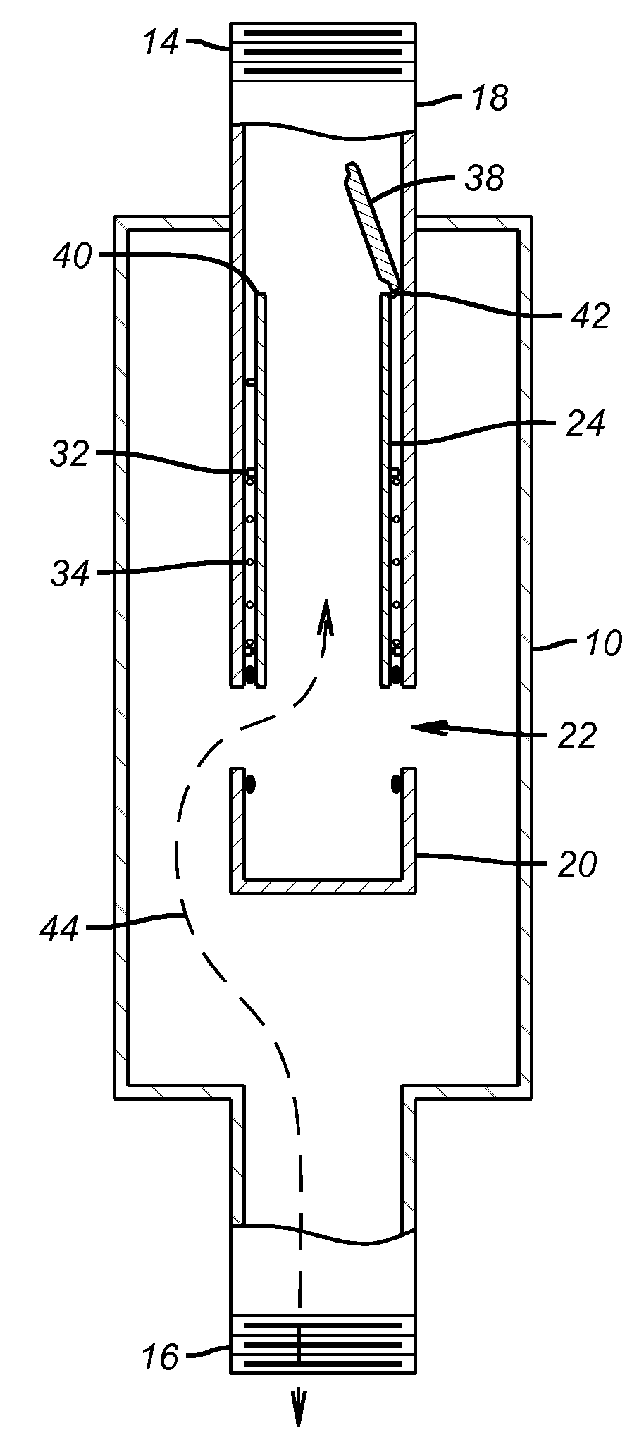
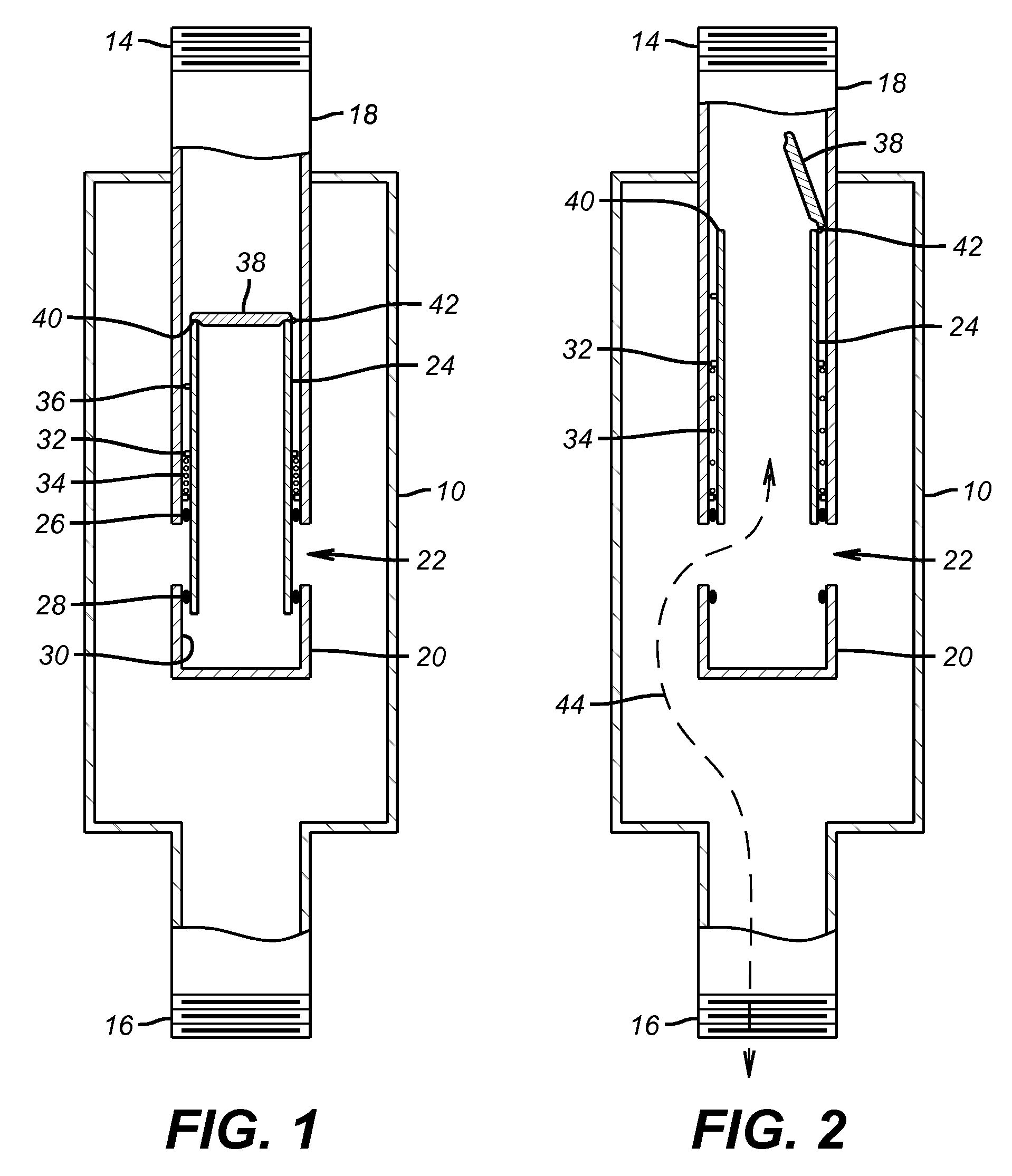
[0008]FIG. 1 is a schematic representation of the valve of the present invention. It features a housing 10 that has end connections 14 and 16 to connect the housing 10 to a production string that is not shown. Connection 14 leads to a tube 18 that has a closed bottom 20 and one or more wall ports 22 above the bottom 20. There is a pressure relieving device (not shown), such as a poppet valve or a spring operated ball check valve that will allow flow from the inside of bottom 20 to the outside of bottom 20, so that when the valve is closed and pressure is applied that will cause the sleeve 24 to move down, fluid will be able to escape through that pressure relieving device so that the sleeve would not be hydraulically locked. Below connection 16 there can be a packer, a screen, or other form of well completion. Formation flow comes in to the inlet connection 16 and reaches the surface through a second connection 14. Sleeve 24 is cycled with applied pressure down the production tubing...


PUM


Abstract

A downhole valve features a flow port that can be selectively obstructed by a pressure actuated sleeve that is movable in a pin and slot mechanism to rotate while being cycled up and down by application and removal of pressure in a cyclical manner. When the sleeve is cycled to the port closed position, a flapper mounted near its upper end can fall on a seat on the sleeve to allow pressure to be applied to the flapper and sleeve, causing the sleeve to move to a position that will prevent fluid loss from the tubular string into the formation. The Closed flapper allows pressure cycles of the sleeve. A double closure against fluid loss can be affected.

Description

FIELD OF THE INVENTION[0001]The field of the invention is downhole valves that can provide bi-directional fluid flow, as well as to prevent fluid loss into the formation and can be opened using only surface pressure to allow production and more particularly valves that can be operated from the surface by pressure so that a surface rig is not needed to stop the possibility of production or fluid loss to the formation.BACKGROUND OF THE INVENTION[0002]Completions in low pressure formations involve a risk of fluid loss into the formation. In these instances the hydrostatic pressure from the liquid column in the production string is higher than the formation pressure. A fluid loss valve selectively keeps the fluid in the production string from flowing into the formation and potentially decreasing its subsequent ability to produce hydrocarbons from the formation. On the other hand, when the formation needs to be produced, the valve must be opened to allow the formation a path to the surfa...

Claims


Application Information

Patent Timeline
IPC IPC(8): E21B34/10
CPCE21B23/006E21B2034/005E21B34/102E21B34/10E21B2200/05
Inventor JASSER, RAMI J.MORTON, ROBERT D.
Owner BAKER HUGHES INC
Why Eureka
Try Eureka