Occupancy wall sensor

a sensor and occupancy wall technology, applied in the field of occupancy wall sensors, can solve the problems of damage to the sensor, difficult adjustment, and inability to readily find tools, and achieve the effects of quick and easy mounting, improved sensor adjustment, and easy replacemen

Inactive Publication Date: 2007-05-01
LEVITON MFG
View PDF4 Cites 25 Cited by
  • Summary
  • Abstract
  • Description
  • Claims
  • Application Information

AI Technical Summary

Benefits of technology

[0010]The present invention helps overcome some of the above problems by providing an occupancy sensor which can be quickly and easily mounted and oriented to scan a specific coverage or scanning area without requiring a special installation tool. The sensor includes a relatively light weight, single piece mounting base which is separate from the body of the sensor and which can be mounted to a structure such as a wall or ceiling without requiring the installer to support the weight of the body of the sensor. Thereafter, the body of the sensor is mounted into the base which is mounted to the wall or ceiling and the sensor body is twist locked to the base to obtain coverage of different scanning areas. Additional adjustments can be made by loosening a threaded fastener such as a nut on the back of the sensor body. To help overcome the damage lens problem, the sensor includes a replaceable PIR lens with a snap on lens holder which can be attached to the sensor.
[0011]In one aspect of the invention, an occupancy sensor is disclosed that includes a base member adapted to be mounted to a structure such as a wall or ceiling, a PIR sensor and a base neck having a first end and a second end. The first end is coupled to the sensor with a ball-socket coupling and the second end is coupled to the base member with a rotating coupling. The ball-socket coupling and the rotatable coupling mechanism provide a combination of two freedoms of rotation for improved sensor adjustment. The lens is part of a replaceable lens holder which allows for easy replacement of a damaged lens. The techniques of the present invention are also applicable to other occupancy sensing technologies such as ultrasonic and microwave means.

Problems solved by technology

Sometimes the tool may not be readily available, particularly when the sensor is being re-positioned or re-oriented some time after first being installed on a wall.
This type of adjustment can not only be difficult to perform, but can sometimes result in damage to the sensor as it is being re-mounted to the wall or being disassembled and then reassembled.
It is usually made of a thin, soft plastic material, the surface of which is prone to being scratched.
The lens is usually relatively large to allow the sensor to cover a scanning area or scan a large field of view and, as the lens is mounted on the front surface of the sensor, it is prone to being damaged.
For example, during the manufacture, shipping, handling and installation of the sensor the lens, which is a delicate and crucial component of the sensor, can be easily scratched or damaged.
A scratched or damaged lens can prevent the sensor from operating properly.
Another problem with current wall mounted sensors is the absence of a simple way of mounting the sensors to a wall or ceiling.

Method used


Image

  • Occupancy wall sensor
  • Occupancy wall sensor
  • Occupancy wall sensor

Examples


Embodiment Construction

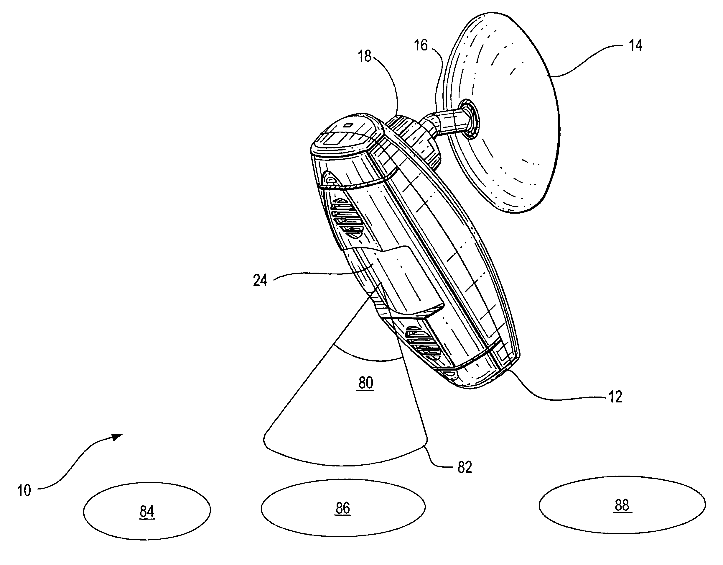
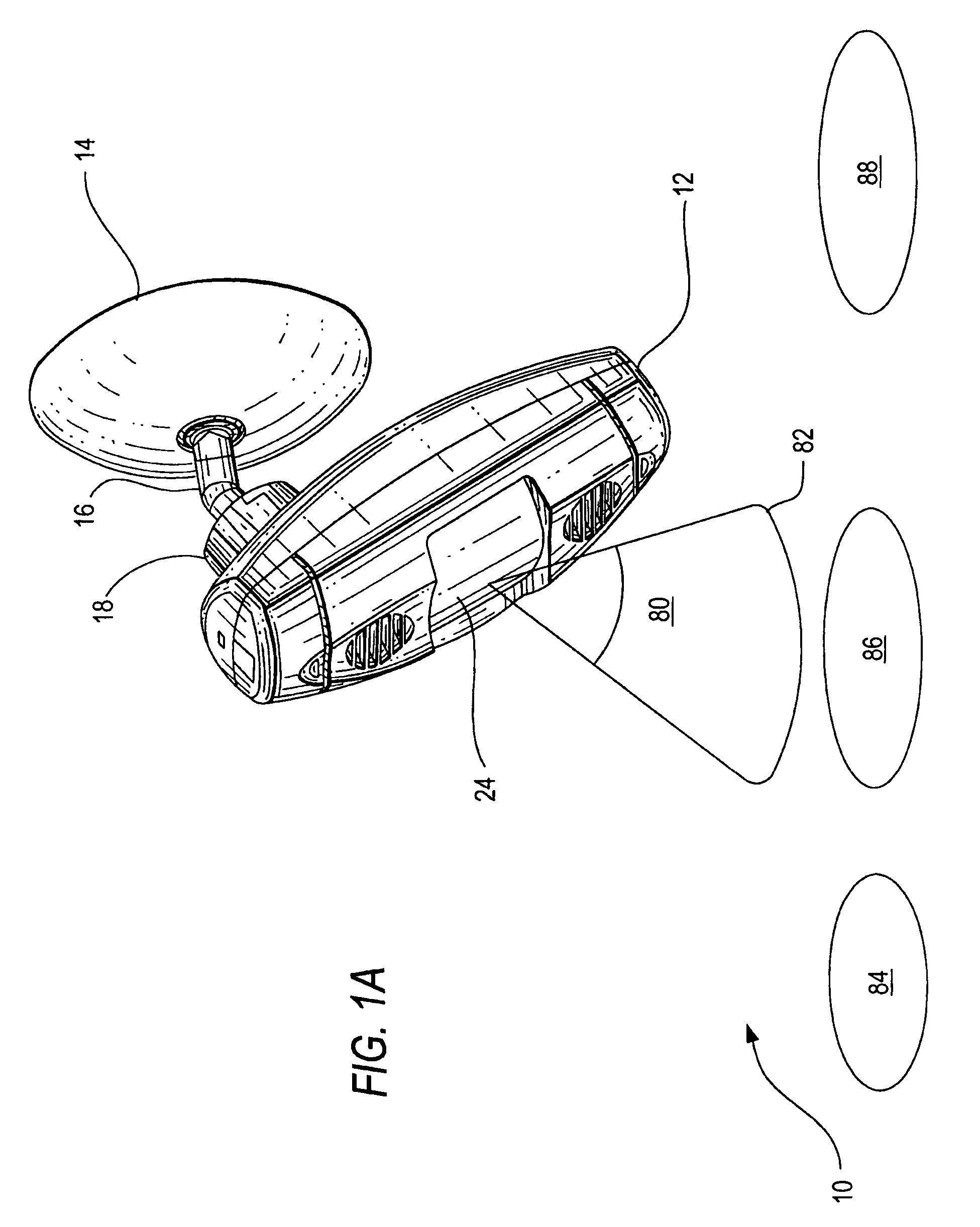
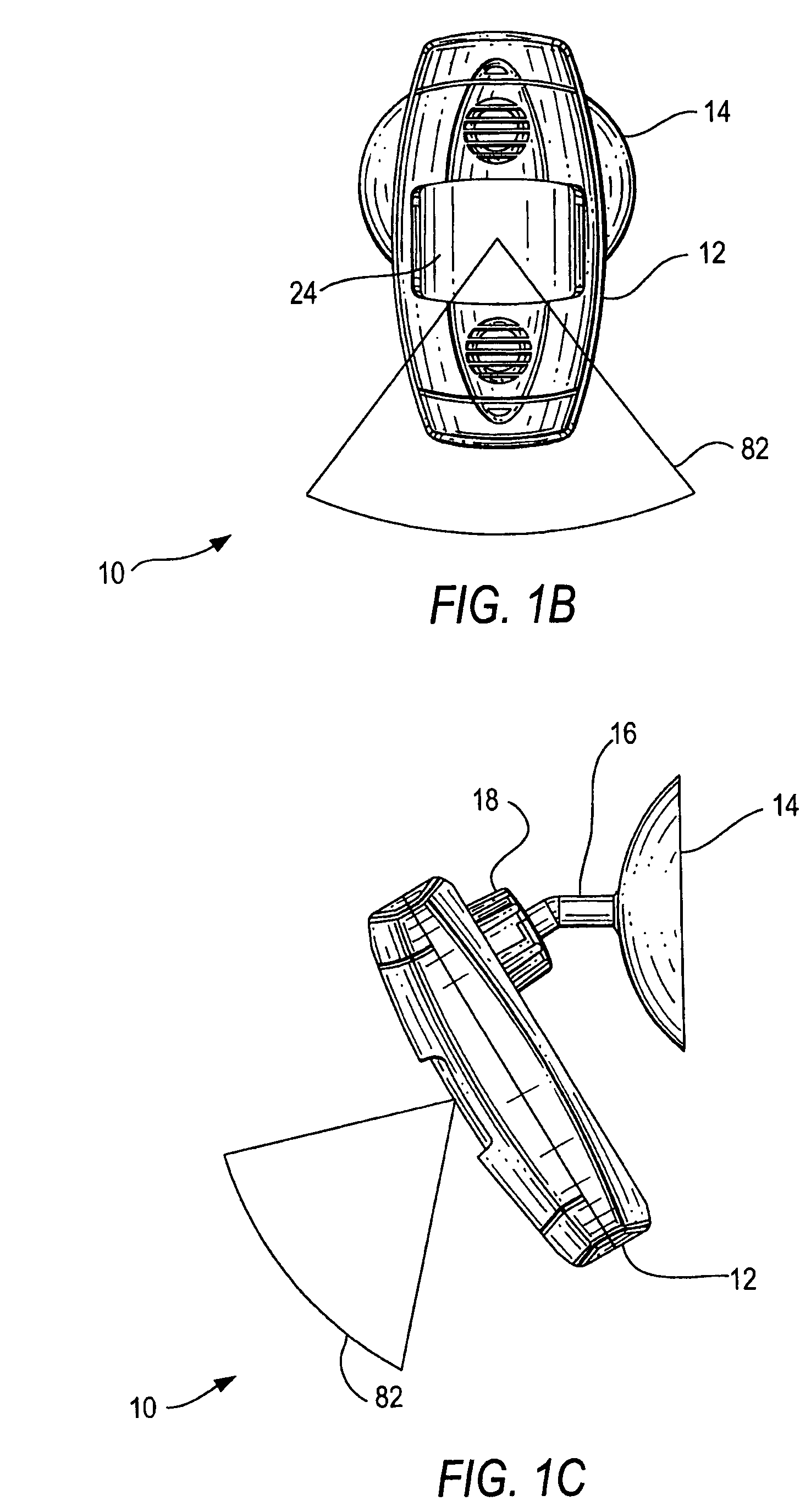
[0021]The present invention discloses an occupancy sensor having a passive infrared (PIR) lens holder coupled to a versatile mounting mechanism for adjusting the scanning or coverage area of the sensor without the use of a tool. The mounting mechanism includes a base neck member having a first end employing a ball-socket coupling to the PIR lens holder sensor body and a second end using a rotatable coupling to a mounting base. The ball-socket coupling and the rotatable coupling mechanism provide a combination of two freedoms of rotation for enhanced sensor adjustment. The lens is part of a replaceable lens holder which allows for easy replacement of a damaged lens. Although one embodiment of the present invention is directed to PIR sensing means, the techniques of the present invention are also applicable to other occupancy sensing technologies such as ultrasonic microwave means or a combination thereof.

[0022]Referring to FIGS. 1A–1D, there is shown different views of an occupancy s...


PUM


Abstract

A sensor mounting mechanism that includes a base member adapted to be mounted to a structure and a base neck having a first end and a second end where the first end is adapted to be coupled to a sensor with a ball-socket coupling and the second end is coupled to the base member with a rotating coupling. The mounting mechanism provides fine and coarse adjustment means for adjusting the scanning area of the sensor such as an PIR occupancy sensor without the use of a tool. The sensor includes a detachable lens holder for easy replacement of the lens.

Description

[0001]This application claims the benefit of the filing date of a provisional application having Ser. No. 60 / 604,543 which was filed on Aug. 26, 2004.BACKGROUND OF THE INVENTION[0002]1. Field of the Invention[0003]The present invention relates to occupancy wall sensors.[0004]2. Description of the Related Art[0005]Normally, newly installed occupancy wall sensors, such as passive infrared (PIR) and / or ultrasonic occupancy wall sensors, when first installed, need to be positioned on a wall or ceiling and then oriented to scan an area of interest to provide the level of protection desired by the user. Frequently, the sensors, after being mounted to the wall or ceiling, must normally then be re-oriented a few times until they actually scan the area desired. Also, as the users needs change, existing wall sensors may need to be re-positioned and re-oriented to scan different areas at, possibly, different viewing angles.[0006]Some current sensors may require a special tool which is provided...

Claims


Application Information

Patent Timeline
Patent Type & Authority Patents(United States)
IPC IPC(8): G01J5/02
CPCG01D11/245G01J5/02G01J5/0205G01J5/04G01J5/08G01J5/0806G01J5/089G08B13/19G01J5/0025G01J5/047Y10S250/01G01J5/07
Inventor WU, YUNBANDRINGA, JOHNSOCCOLI, PAULSHAH, NEHALLOMBARDI, ALFRED J.UFTRING, EDWARDKEVELOS, ADAM
Owner LEVITON MFG
Why Eureka
Try Eureka