
Optical substance analyzer

a substance analyzer and optical technology, applied in the field of sensors, can solve the problems of inability to adapt to use outside the laboratory, inability to adapt to portable use, and laborious, and achieve the effect of large differential phase shift and advantageously high sensitivity to the pathogen

Active Publication Date: 2007-05-01
LUCENT TECH INC +1
View PDF4 Cites 10 Cited by
  • Summary
  • Abstract
  • Description
  • Claims
  • Application Information

AI Technical Summary

Benefits of technology

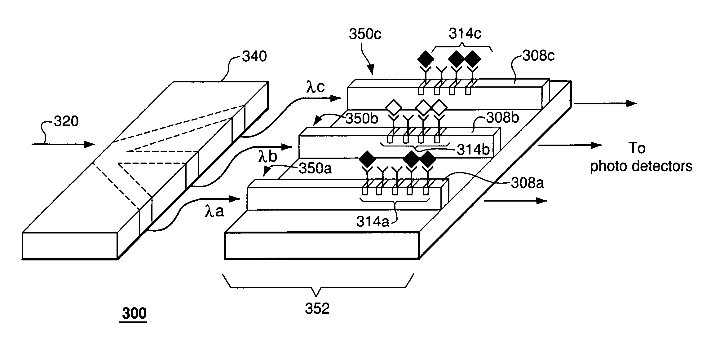
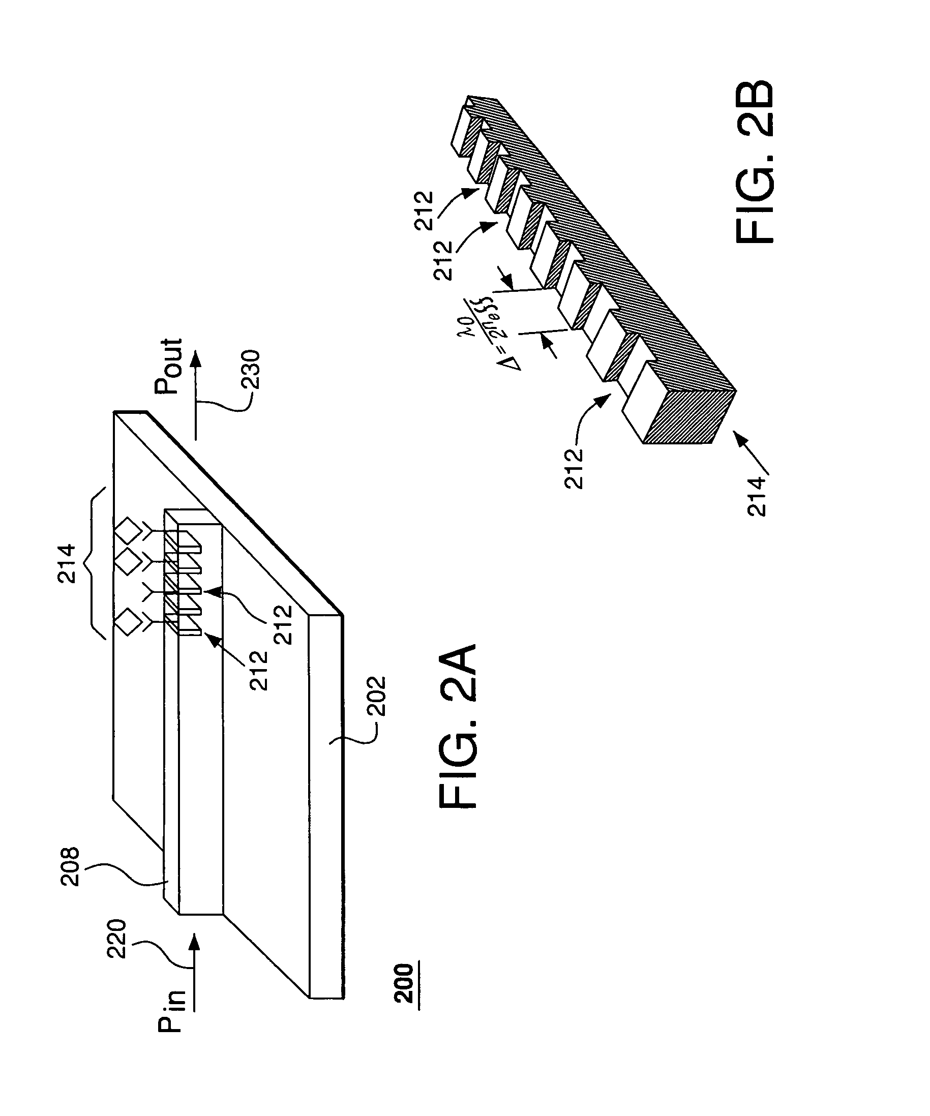
[0006]Problems in the prior art are addressed, in accordance with the principles of the present invention, by a portable waveguide sensor having one or more gratings adapted to cause a change in the optical characteristics of the sensor in the presence of a particular substance of interest, e.g., a biological pathogen. In one embodiment, the sensor has a waveguide, wherein a plurality of grooves imprinted onto the waveguide form a Bragg grating. The surface of the grooves has a functional layer adapted to bind the pathogen. When the pathogen binds to the functional layer, the binding shifts the spectral reflection band corresponding to the Bragg grating such that a probe light previously reflected by the grating now passes through the grating, thereby indicating the presence of the pathogen. In another embodiment, the sensor has a Mach-Zehnder interferometer (MZI), one arm of which has a resonator formed by two Bragg gratings. The surface of the resonator between the gratings has a functional layer whereas the Bragg gratings themselves do not have such a layer. Due to multiple reflections within the resonator, light coupled into the MZI interacts with the bound pathogen over a relatively large effective propagation length, which results in a relatively large differential phase shift and therefore advantageously high sensitivity to the pathogen.

Problems solved by technology

Since exposure to these pathogens is a health hazard, low concentrations, typically trace amounts, need to be detected quickly and reliably.
However, the available techniques are often time-consuming, labor-intensive, and / or relatively expensive.
In addition, devices implementing these techniques are not adapted for portable use, nor are they adapted for use outside the laboratory.

Method used


Image

  • Optical substance analyzer
  • Optical substance analyzer
  • Optical substance analyzer

Examples


Embodiment Construction

[0011]Reference herein to “one embodiment” or “an embodiment” means that a particular feature, structure, or characteristic described in connection with the embodiment can be included in at least one embodiment of the invention. The appearances of the phrase “in one embodiment” in various places in the specification are not necessarily all referring to the same embodiment, nor are separate or alternative embodiments mutually exclusive of other embodiments.

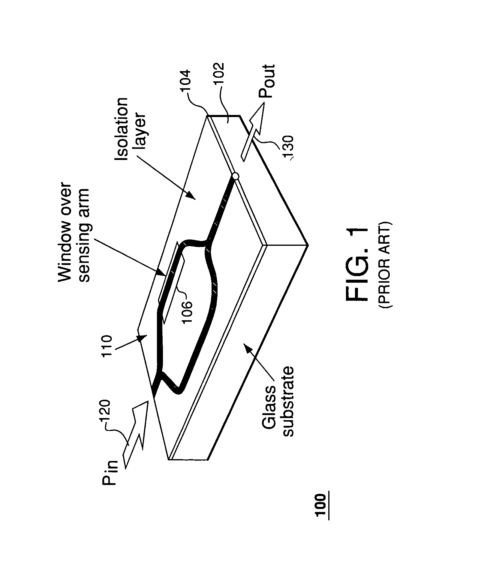
[0012]FIG. 1 shows a perspective three-dimensional view of a prior-art optical sensor 100 disclosed in an article by B. J. Luff, et al., published in J. Lightwave Technology, 1998, Vol. 16, No. 4, p. 583, the teachings of which are incorporated herein by reference. Sensor 100 is a planar waveguide device having a Mach-Zehnder interferometer (MZI) 110 formed on a glass substrate 102. An isolation layer 104 that covers MZI 110 has an opening 106, which exposes one arm of the MZI to the environment, while keeping the other arm protect...


PUM

PropertyMeasurementUnit
reflectivityaaaaaaaaaa
optical characteristicsaaaaaaaaaa
center wavelengthaaaaaaaaaa

Abstract

A portable waveguide sensor having one or more gratings. In one embodiment, the sensor has a waveguide, wherein a plurality of grooves imprinted onto the waveguide form a Bragg grating. The surface of the grooves has a functional layer adapted to bind a substance of interest, e.g., a biological pathogen. When the pathogen binds to the functional layer, the binding shifts the spectral reflection band corresponding to the Bragg grating such that a probe light previously reflected by the grating now passes through the grating, thereby indicating the presence of the pathogen. In another embodiment, the sensor has a Mach-Zehnder interferometer (MZI), one arm of which has a resonator formed by two Bragg gratings. The surface of the resonator between the gratings has a functional layer whereas the Bragg gratings themselves do not have such a layer.

Description

BACKGROUND OF THE INVENTION[0001]1. Field of the Invention[0002]The present invention relates to sensors and, more specifically, to optical devices for detecting chemical and biological substances.[0003]2. Description of the Related Art[0004]Substance analyzers are used in environmental monitoring, industrial process control, and medical, analytical, and military applications. For example, biological pathogens such as salmonella are often present in meat and poultry products. Since exposure to these pathogens is a health hazard, low concentrations, typically trace amounts, need to be detected quickly and reliably.[0005]In an analytical laboratory, specialized techniques such as mass spectrometry, chromatography, electro-chemical analysis, immunoassays, etc., are readily available to detect various chemical and biological substances (i.e., analytes) with great sensitivity and specificity. However, the available techniques are often time-consuming, labor-intensive, and / or relatively e...

Claims


Application Information

Patent Timeline
Patent Type & Authority Patents(United States)
IPC IPC(8): G02B6/00G01N21/27G01N21/43G01N21/45G01N21/77G01N33/543G01N33/569
CPCG01N21/45G01N21/774G01N33/54366G01N33/569G01N21/7746G01N2021/7709G01N2021/7779G01N2021/7793G01N33/543
Inventor CARR, DUSTIN W.CHAN, HO BUNTRAN, ALEX T.
Owner LUCENT TECH INC
Learn More