Cable element having repositionable pressure sensitive adhesive to couple buffer tubes to a central strength member

a buffer tube and adhesive technology, applied in the field of optical cable elements, can solve the problems of affecting the access of buffer tubes of related art, exposing optical fibers to radial stresses, and stranding materials causing undesirable stresses on buffer tubes, so as to reduce the amount of packaging, eliminate stranding materials and the stranding step, and improve the effect of access

Active Publication Date: 2007-05-01
DRAKA COMTEQ BV
View PDF13 Cites 34 Cited by
  • Summary
  • Abstract
  • Description
  • Claims
  • Application Information

AI Technical Summary

Benefits of technology

[0005]The present invention is directed to a cable element that addresses the problems discussed above, as well as others. Specifically, the present invention relates to a cable element that reduces the amount of packaging, eliminates stranding materials and the stranding step, and improves access, particularly, access in the field. Additionally, the present invention eliminates binder materials and water swellable materials, and correspondingly, eliminates the stresses that would be induced on the buffer tubes by such binder materials or water swellable materials.
[0006]To overcome the problems associated with the related art cable elements, the present invention provides buffer tubes that are bonded adhesively to a central strength member, thereby eliminating the stranding material and the stranding step, as well as the stresses resulting therefrom. More particularly, the present invention couples the buffer tubes to the central strength member using a pressure sensitive adhesive that is a repositionable adhesive. In the present invention, the individual buffer tubes can be removed and reapplied to the central strength member, thereby permitting the buffer tubes to be kept in a more ordered cylindrical structure.

Problems solved by technology

However, the related art optical cable elements have several disadvantages.
Thus, the cable elements of related art have the adverse effect of exposing the optical fibers to radial stresses that are applied during further manufacturing steps.
Thus, the buffer tubes of the related art can be difficult to access in the field.
Further, the binders or other similar stranding materials induce undesirable stresses on the buffer tubes.

Method used


Image

  • Cable element having repositionable pressure sensitive adhesive to couple buffer tubes to a central strength member
  • Cable element having repositionable pressure sensitive adhesive to couple buffer tubes to a central strength member
  • Cable element having repositionable pressure sensitive adhesive to couple buffer tubes to a central strength member

Examples


Embodiment Construction

[0013]Hereinafter, illustrative, non-limiting embodiments of the present invention will be described in detail with reference to the attached drawings. The present invention is not restricted to the following illustrative embodiments, and many variations are possible within the spirit and scope of the present invention. Illustrative embodiments of the present invention are provided in order to more completely explain the present invention to one skilled in the art.

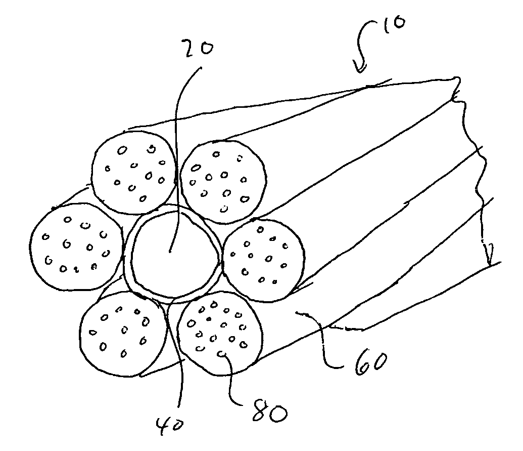
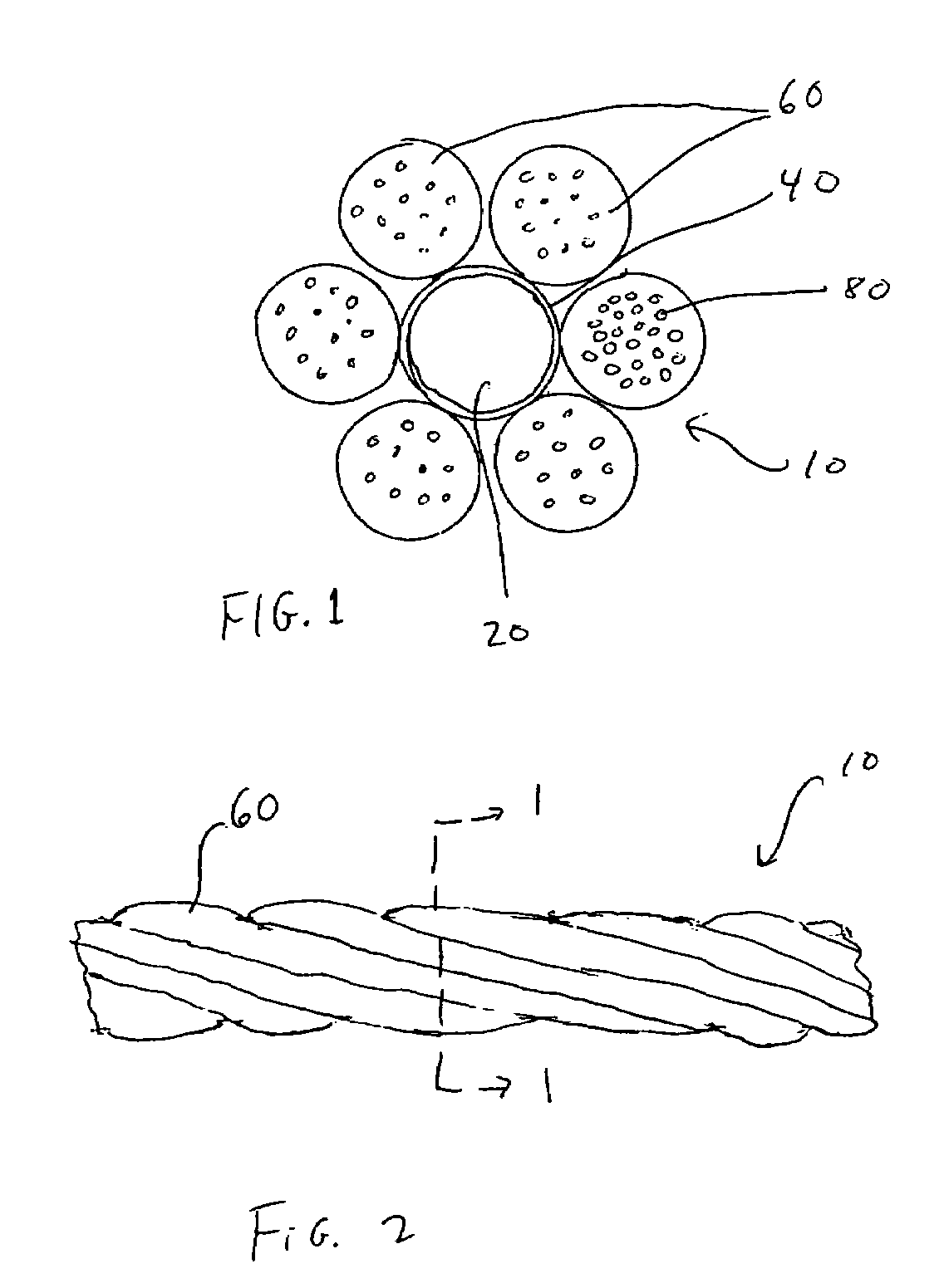
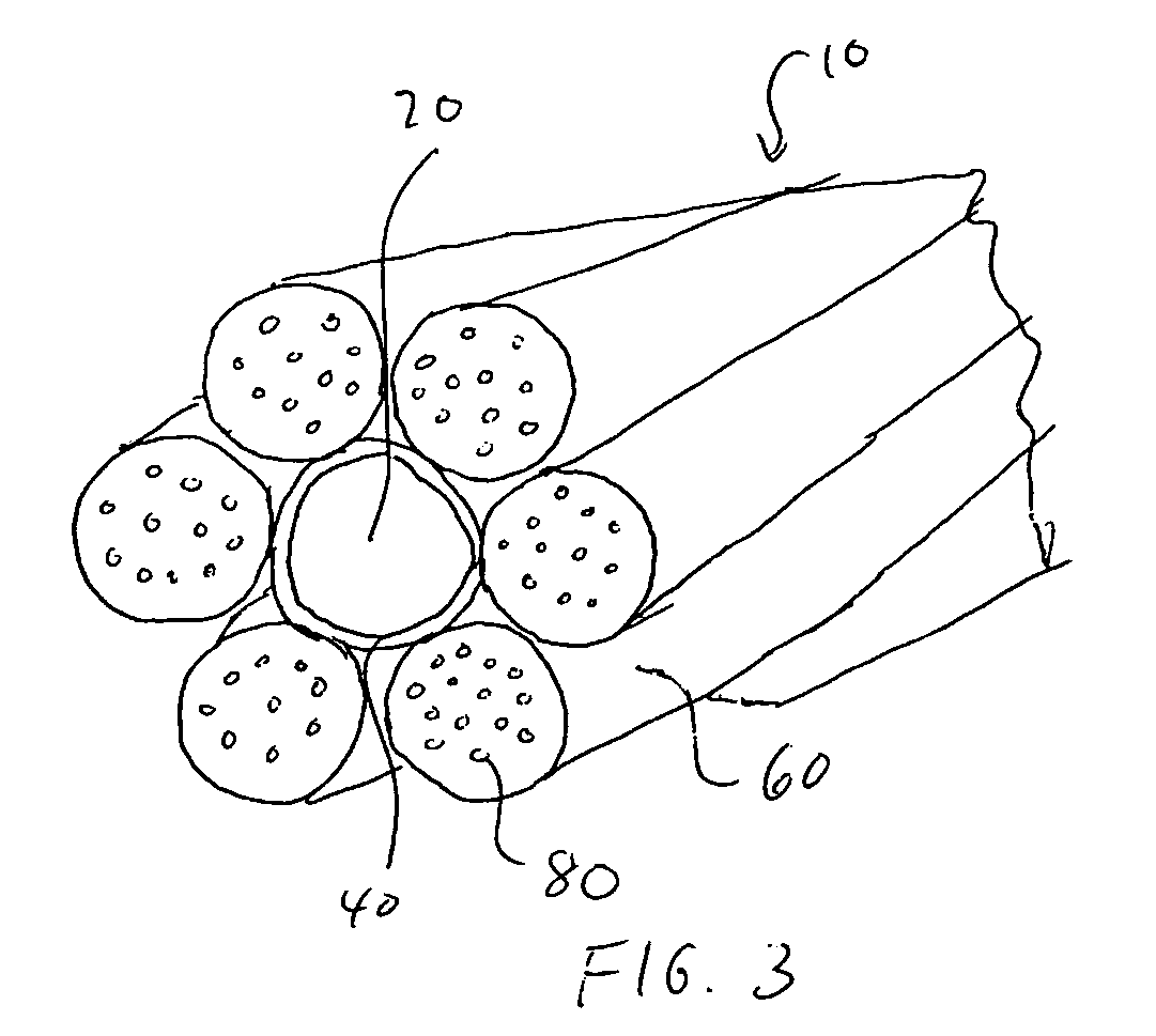
[0014]FIG. 1 is a cross-section showing the buffer tubes bonded to the central strength member, such as a GRP. The buffer tubes are bonded across the length and have the applied twist from the oscillator. FIG. 2 is a side view according to an illustrative, non-limiting embodiment of the present invention. FIG. 3 is a perspective view according to yet another illustrative, non-limiting embodiment of the present invention.

[0015]As shown in the illustrative, non-limiting embodiment of the present invention depicted in FIG. 1,...


PUM


Abstract

A cable element and a method of making the same, in which the cable element has a central strength member, a plurality of buffer tubes are disposed on the central strength member, each of the plurality of buffer tubes encloses at least one signal transmission element, and a layer of pressure sensitive adhesive is provided on the central strength member. The pressure sensitive adhesive is a repositionable adhesive and releasably couples the plurality of buffer tubes to the central strength member such that the plurality of buffer tubes can be coupled and uncoupled repeatedly from the central strength member.

Description

FIELD OF THE INVENTION[0001]The present invention relates to an cable element having buffer tubes that easily are removable and re-applicable to a central strength member (CSM). In particular, the present invention relates to an optical cable element using a repositionable pressure sensitive adhesive to couple buffer tubes to a central strength member, such as a glass reinforced plastic (GRP).BACKGROUND OF THE INVENTION[0002]Currently, a need exists to reduce the amount of packaging of optical cable elements and to develop optical cable elements with finger accessible buffer tubes that can be accessed easily in the field by a field technician. In the related art, buffer tubes are stranded (for example, helically or reverse helically) around a central strength member to form a stranded core. The thin walled buffer tubes are bound to the central strength member using a binder, yarn, or thread. In addition, each of the buffer tubes house an optical unit, such as one or more optical fib...

Claims


Application Information

Patent Timeline
Patent Type & Authority Patents(United States)
IPC IPC(8): G02B6/44
CPCG02B6/4434G02B6/441
Inventor DALLAS, GEORGEROLLET, BENOITMEISCH, CHRISTOPHEPOUILLY, SERGE
Owner DRAKA COMTEQ BV
Why Eureka
Try Eureka