Control mechanism for a socket wrench

a control mechanism and socket wrench technology, applied in the field of socket wrench control mechanism, can solve the problems of poor torque and strength, failure to precisely control the torque, and the operation of the wrench in a very limited space, so as to prevent the failure of the torque control and the effect of effective control mechanism

Inactive Publication Date: 2007-05-08
TSAI CHEN CHANG
View PDF6 Cites 14 Cited by
  • Summary
  • Abstract
  • Description
  • Claims
  • Application Information

AI Technical Summary

Benefits of technology

[0005]The primary purpose of the present invention is to provide an effective control mechanism for a torque-indicating socket wrench that is capable of safe, high efficiency, high strength torque control while eliminating the problem of losing control due to improperly applied external force.
[0007]Yet another purpose of the present invention is to provide an effective control mechanism for a torque-indicating socket wrench that prevents failure of the torque control. To achieve the purpose, the auxiliary positioning lever effectively contains the socket after the socket rotates to fend off abnormal falling off position by the spring compressed due to improper application of force or vibration from external source to ensure the solid control of the direction and positioning of the force applied.
[0008]Still another purpose of the present invention is to provide an effective control mechanism for a torque-indicating socket wrench that prevents skid to secure effective transmission of torque. To achieve the purpose, a segment channel is provided in the box to facilitate the slide of the roller.

Problems solved by technology

However, the major flaw of the ratchet type socket wrench is that it is prevented from operating in a very limited space for being subject to the angle of the serration.
However, the roller type socket wrench is vulnerable to become out of control thus to cause injury to the user when subject to improperly or excessively applied external force.
Furthermore, the simple construction often results in poor torque and strength to fail the exact control of torque.
Therefore, either the ratchet or the roller type of socket wrench fails to meet the design requirements of high torque, high strength, and minute working space today.

Method used


Image

  • Control mechanism for a socket wrench
  • Control mechanism for a socket wrench
  • Control mechanism for a socket wrench

Examples


Embodiment Construction

[0020]The following descriptions are of exemplary embodiments only, and are not intended to limit the scope, applicability or configuration of the invention in any way. Rather, the following description provides a convenient illustration for implementing exemplary embodiments of the invention. Various changes to the described embodiments may be made in the function and arrangement of the elements described without departing from the scope of the invention as set forth in the appended claims.

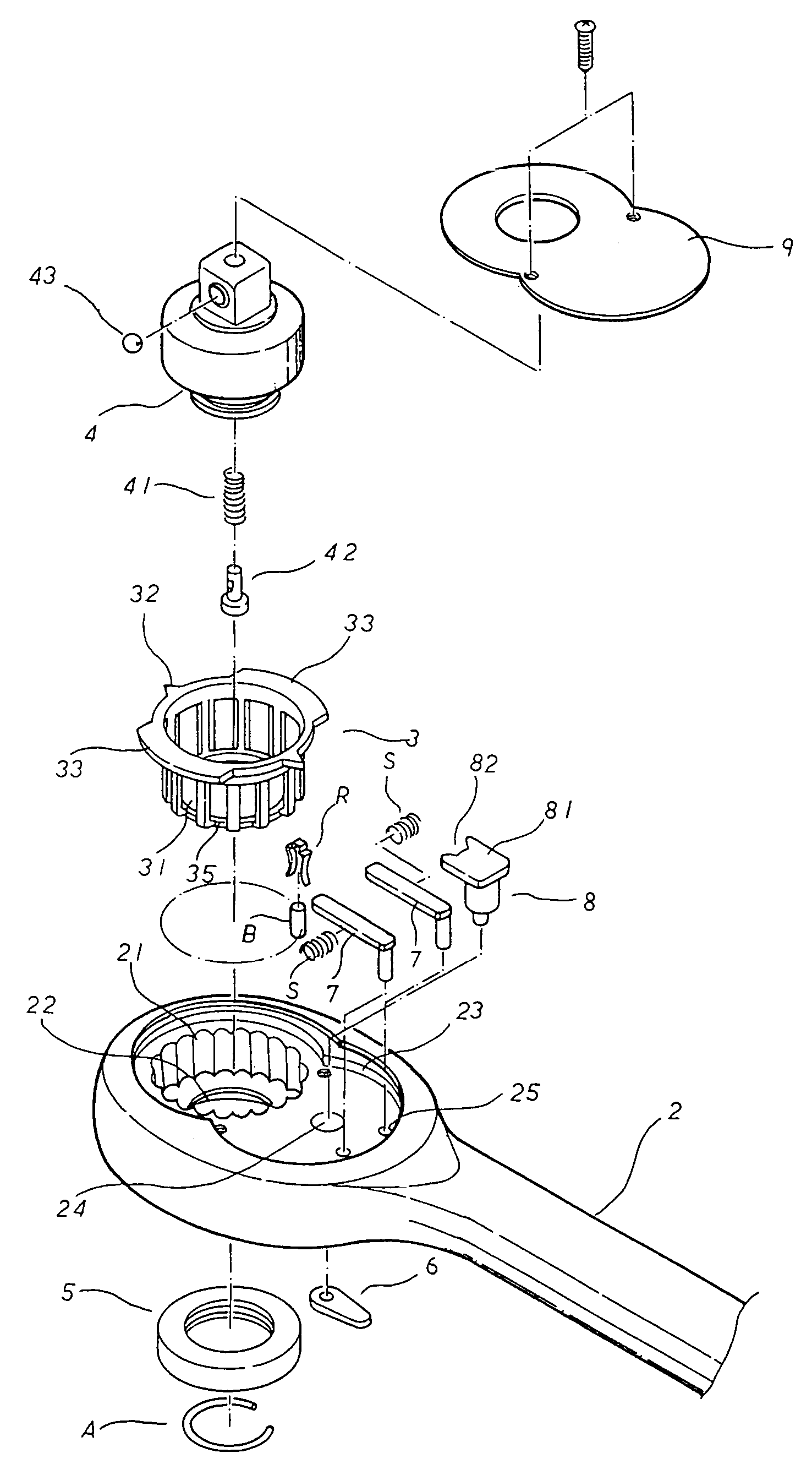
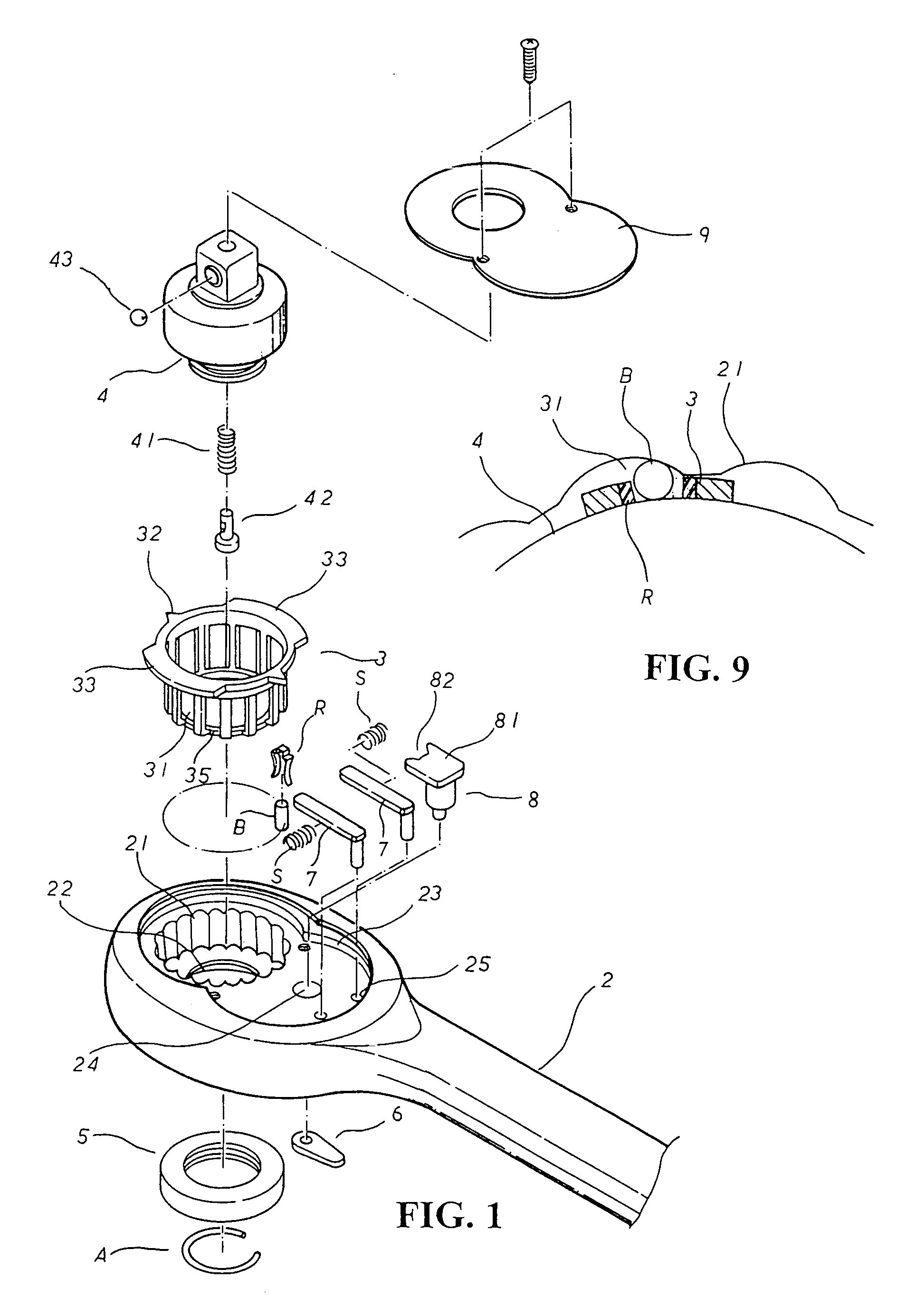
[0021]Referring to the accompanying drawings, a first preferred embodiment of the present invention is essentially comprised of a handle 2, a socket 3, an inner rotor 4, a C-washer A, a ring spacer 5, a dialer 6, an auxiliary positioning lever 7, a control 8, a spring S, a lid 9, a roller B and an elastic member R. Wherein, one or multiple segment channel 21 is provided to one end of the handle 2 to accommodate the socket 3 and the inner rotor 4. One or multiple resilient member R and one or mult...


PUM


Abstract

An effective control mechanism for a socket wrench that is capable of safe, high efficiency, high strength torque control while eliminating the problem of losing control due to improperly applied external force. The control mechanism includes a handle, a socket, an inner rotor, a C-washer, a ring spacer, a dialer, left and right auxiliary positioning levers, a control, a spring, a lid, a roller, and an elastic member; wherein an end of the handle includes a segment channel to accommodate the socket and the inner rotor, the socket includes one or multiple elastic member and one or multiple roller in relation to the segment channel, and multiple locking holes being provided on the recessed surface of the end of the handle for installation of both of the left and the right auxiliary positioning levers and the spring.

Description

BACKGROUND OF THE INVENTION[0001](a) Technical Field of the Invention[0002]The present invention is related to a control mechanism for a socket wrench, and more particularly to one which provides safe, high efficiency, and high strength torque control.[0003](b) Description of the Prior Art[0004]Socket wrenches generally available in the market are generally classified into two types, ratchet and roller. The ratchet type operates on having an inner rotor having a serrated surface adapted with a control mechanism comprised of left and right retainers, spring and rotor, primary control and box of the wrench. However, the major flaw of the ratchet type socket wrench is that it is prevented from operating in a very limited space for being subject to the angle of the serration. As for the roller type socket wrench operates on a simple construction of socket, roller and inner rotor. Wherein, pits and steel beads are provided on the rotor and pressure spring being provided to work with thos...

Claims


Application Information

Patent Timeline
Patent Type & Authority Patents(United States)
IPC IPC(8): B25B13/46
CPCB25B13/463
Inventor TSAI, CHEN-CHANG
Owner TSAI CHEN CHANG
Why Eureka
Try Eureka