
Triangle clipping for 3D graphics

a 3d graphics and triangle clipping technology, applied in the field of 3d graphics and triangle clipping, can solve the problems of more than 3 billion bits per second, the computational and data transfer burden of placing the correct data into the frame buffer can still be very large, and the amount of data which must be moved around is very sizable, so as to save storage, eliminate the ping-pong effect, and save computation time and storage space.

Inactive Publication Date: 2007-05-08
RPX CORP
View PDF5 Cites 18 Cited by
  • Summary
  • Abstract
  • Description
  • Claims
  • Application Information

AI Technical Summary

Benefits of technology

The patent text describes a computer system for creating and displaying computer graphics. The system uses a frame buffer to store data for the display. The technical problem addressed in the patent is the heavy computational and data-transfer burden of performing the necessary calculations and operations to prepare the image for display. The text also explains the process of transforming a 3D model into a 2D model for display and the challenges involved in creating a realistic and visually appealing image.

Problems solved by technology

Nevertheless, the amounts of data which must be moved around are very sizable, and the computational and data-transfer burden of placing the correct data into the frame buffer can still be very large.
This implies manipulation of more than 3 billion bits per second, without allowing for any of the actual computations being performed.
Slow rendering will make the rotation or zoom appear jerky.
This is highly undesirable.
The rendering requirements of three-dimensional graphics are particularly heavy.
(For example, color values will need to be interpolated across a triangle or other geometric structure constituting the objects of a graphic) These computational tasks tend to burden the rendering process.
Displaying a 3D graphics image is much more difficult than displaying a traditional 2D image.
3D graphics takes a great deal of computer processing power and memory.
As can be imagined, a fast-paced game needing to maintain a high frame rate will demand a great deal of geometry processing.
As scene complexity increases (more polygons) the computational requirements increase as well.
Setup is the last stage before rasterization, or drawing, and can consume considerable processing time.
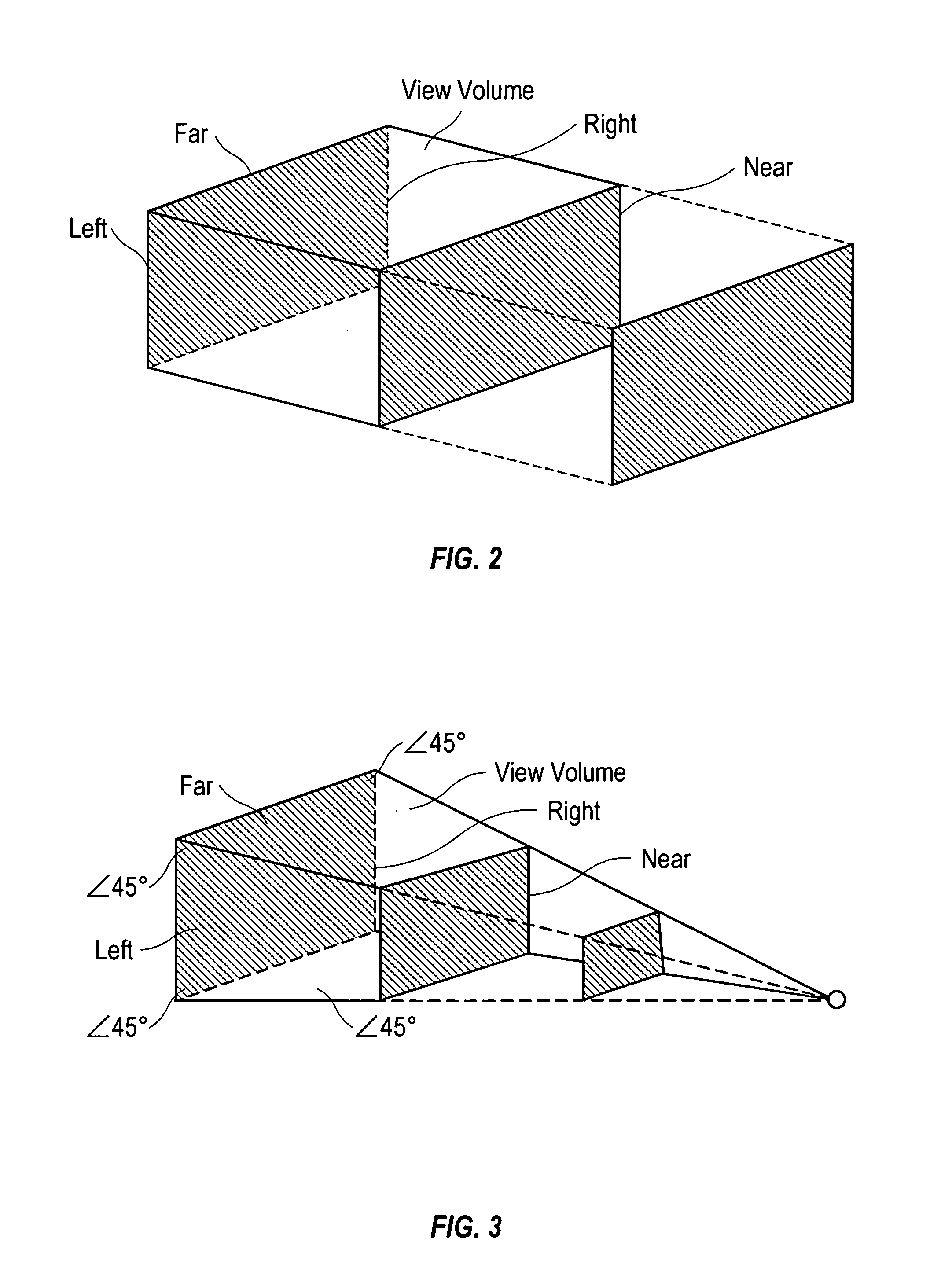
Clipping of a point results in the point being either outside or inside the viewing frustrum.
Clipping of polygons may result in more than one polygon being within the frustrum.
The Sutherland and Hodgman algorithm can be made recursive, however, it offers no real advantages in terms of performance or storage.
Thus, computationally intensive steps are saved.

Method used


Image

  • Triangle clipping for 3D graphics
  • Triangle clipping for 3D graphics
  • Triangle clipping for 3D graphics

Examples


Embodiment Construction

[0069]The numerous innovative teachings of the present application will be described with particular reference to the presently preferred embodiment (by way of example, and not of limitation), in which:

Preferred System Context

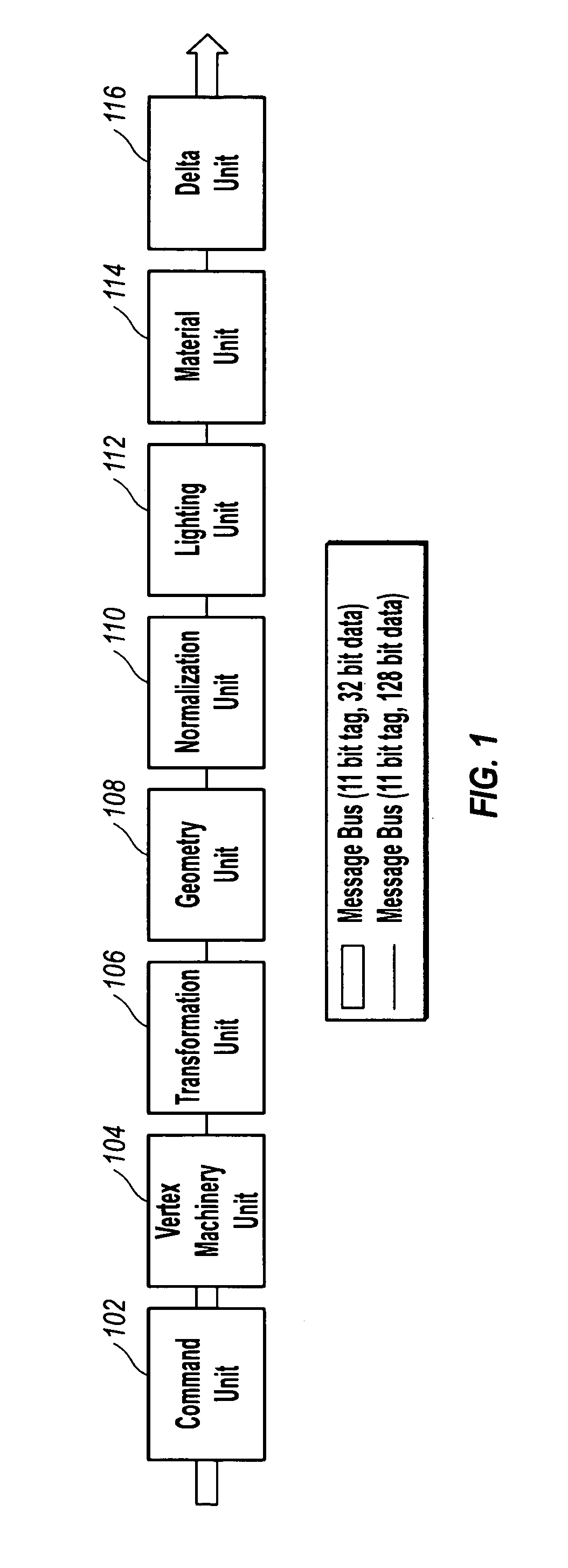
[0070]The system context of the presently preferred embodiment is a GAMMA 3D Geometry and Lighting Accelerator chip for 3D graphics rendering using, among others, the OpenGL, Direct 3D, and QuickDraw 3D applications programming interfaces (APIs). The Hardware Reference Manual and Programmer's Reference Manual for this chip describe further details of this sample embodiment, and are both hereby incorporated by reference. Both are available, as of the effective filing date of this application, from 3Dlabs Inc. Ltd., 181 Metro Drive, Suite 520, San Jose, Calif. 95110. The geometry and lighting functions of graphics rendering are traditionally performed by the host computer. However, the GAMMA 3D Geometry and Lighting Accelerator is designed to be used in conjuncti...


PUM


Abstract

A geometry and lighting graphics accelerator with an improved clipping process. Clipping is performed prior to any calculation or evaluation of primitives for lighting, texture, fog, or color. Barycentric coordinates are used to define all vertices: original, intermediate, and final intersection points. Use of barycentric coordinates results in less storage space. A circular buffer is used during the clipping process to store input and output polygons. Use of the circular buffer also results is reduced storage requirements.

Description

CROSS-REFERENCE TO RELATED APPLICATION[0001]This application claims priority from 60 / 071,590, filed Jan. 15, 1998, which is hereby incorporated by reference.BACKGROUND AND SUMMARY OF THE INVENTION[0002]The present application relates to graphics rendering hardware for computer graphics and animation systems, and particularly to clipping of such graphics in preparation for rendering.Computer Graphics and Rendering[0003]Modern computer systems normally manipulate graphical objects as high-level entities. For example, a solid body may be described as a collection of triangles with specified vertices, or a straight line segment may be described by listing its two endpoints with three-dimensional or two-dimensional coordinates. Such high-level descriptions are a necessary basis for high-level geometric manipulations, and also have the advantage of providing a compact format which does not consume memory space unnecessarily.[0004]Such higher-level representations are very convenient for p...

Claims


Application Information

Patent Timeline
Patent Type & Authority Patents(United States)
IPC IPC(8): G09G5/00G06T15/30
CPCG06T15/30
Inventor BALDWIN, DAVID ROBERT
Owner RPX CORP
Learn More