Oven rack with slide assembly

a technology of extension rack and slide assembly, which is applied in the field of extension rack assembly, can solve the problems of increasing the difficulty of rack movement, affecting the motion of the rack, and not always providing smooth and relatively effortless motion

Inactive Publication Date: 2007-05-15
STANDARD PURISHIJIYAN
View PDF13 Cites 53 Cited by
  • Summary
  • Abstract
  • Description
  • Claims
  • Application Information

AI Technical Summary

Problems solved by technology

Movement of the racks on the ledges, or through other friction mechanisms, may not always provide smooth and relatively effortless motion.
Unconformities in the ledges or friction mechanisms may interfere with motion of a rack.
Similarly, food or other items may become lodged in a rack pathway, increasing the difficulty in movement of the rack.
In addition, the racks often may not be extended very far from the oven, particularly when heavy items are placed on the rack.
Since the racks must still be supported by the ledges of the oven, over extension of the rack may lead to disastrous results, with the rack and its contents dropping to perhaps the floor.
Moreover, the items on the rack may be difficult to view or handle if the rack is partially in the oven.
This increases the chances of burns occurring to users of the oven through contact with other racks or the side walls of the oven.

Method used


Image

  • Oven rack with slide assembly
  • Oven rack with slide assembly
  • Oven rack with slide assembly

Examples


Embodiment Construction

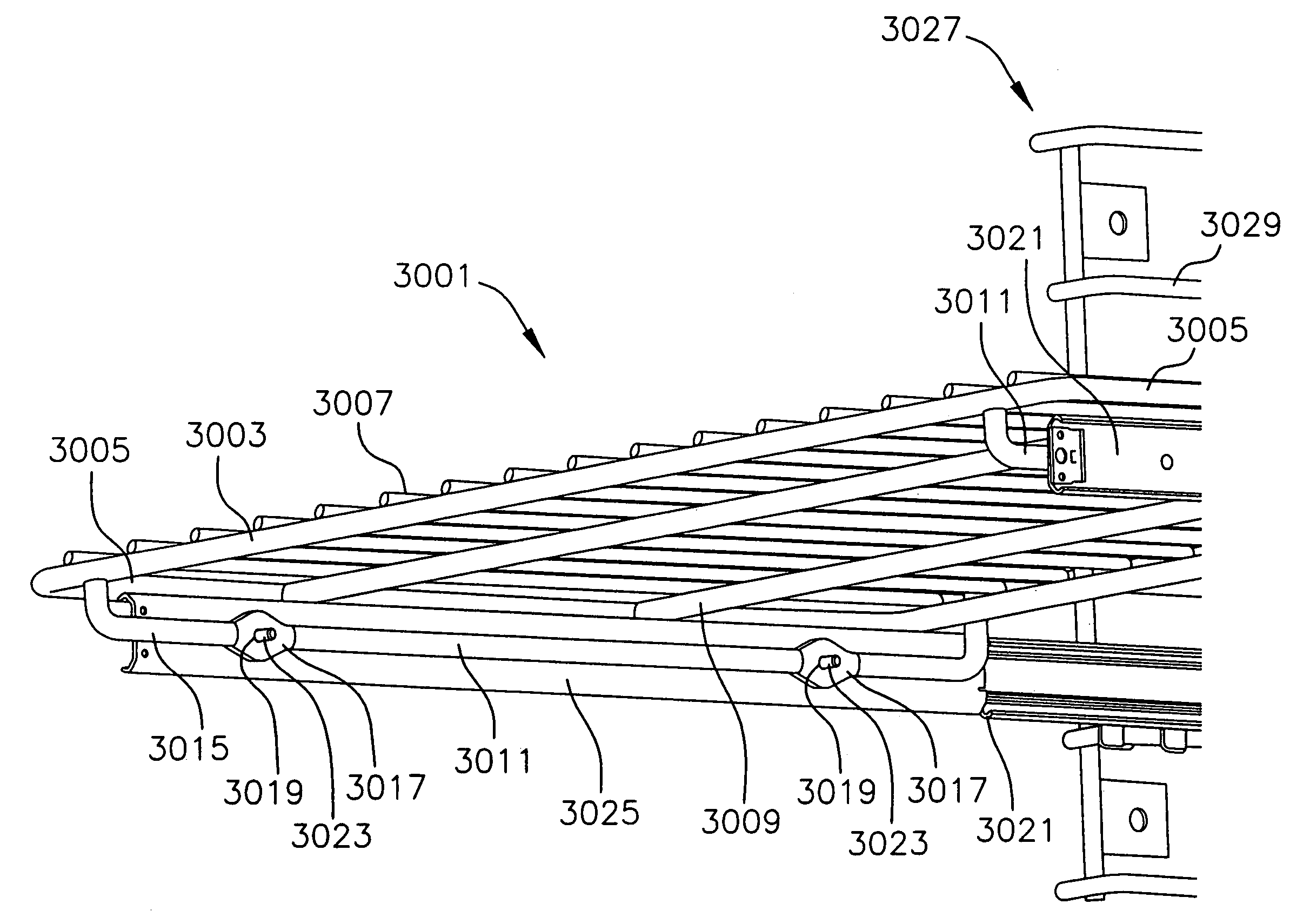
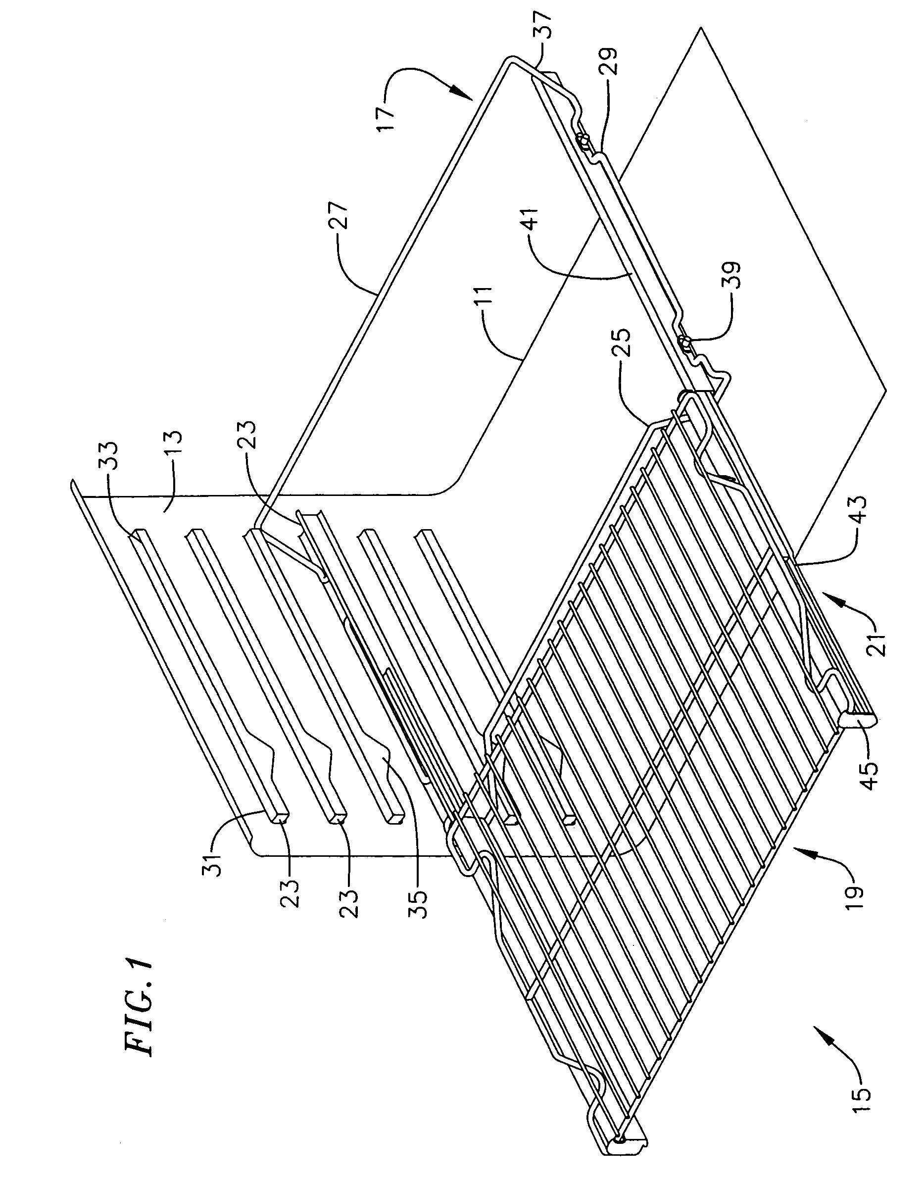
[0036]FIG. 1 illustrates a partial view of an oven. As illustrated, the oven includes a base 11 and a side wall 13. Not specifically illustrated, but known to many, is a back wall of the oven, a roof of the oven, an opposing side wall opposing the side wall illustrated, and a door across the front of the oven. These elements of the oven are not specifically illustrated, although known, so as to allow further view of a rack assembly 15 used in the oven. The rack assembly includes a rack frame 17 supported within the oven, a rack 19 to support cookware, and extendable slides 21 interconnecting the rack and the rack frame. In use the rack frame remains seated within the oven, and the rack may be extended from the oven using the extendable slides.

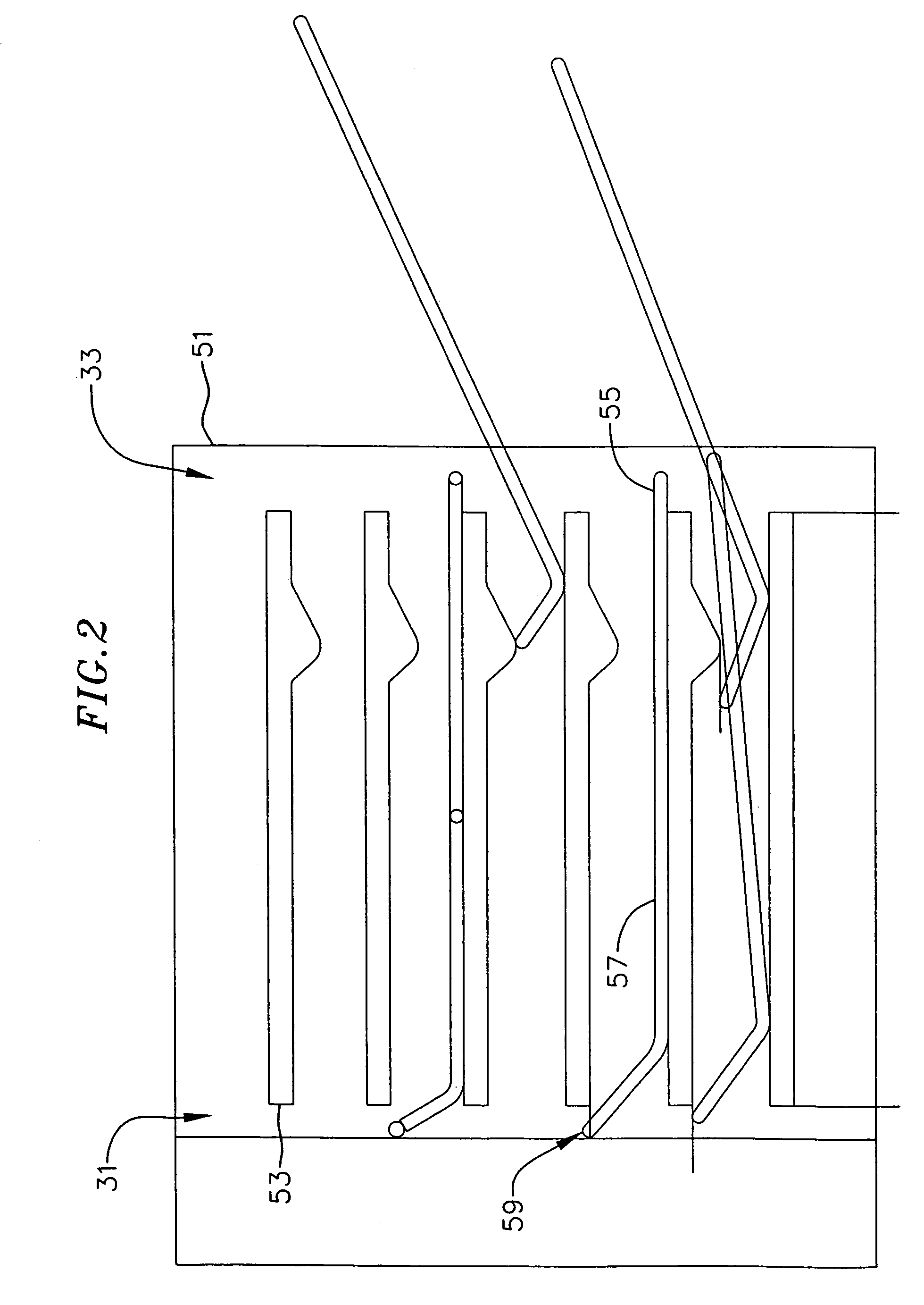
[0037]In the oven of FIG. 1, the rack frame rests on ledges 23 on the oven sidewalls. The rack frame forms a substantially rectangular shape of tubular metal, with a front bar 25, a rear bar 27, and side bars 29 connecting the front and rear ba...


PUM


Abstract

An oven rack assembly including full extension slides. Full extension slides are mounted to an oven rack and oven rack frames or wire racks providing full extension of an oven rack from an oven enclosure. The rack frame is mounted to oven walls or the slides are coupled to wire racks along oven slide walls.

Description

CROSS REFERENCE TO RELATED APPLICATION[0001]This application claims the benefit of U.S. Provisional Application No. 60 / 407,102, filed Aug. 29, 2002 and is a continuation-in-part of U.S. patent application Ser. No. 10 / 617,493, filed Jul. 10, 2003, entitled Oven Assembly With Slides, which claims the benefit of U.S. Provisional Application No. 60 / 395,204, filed Jul. 10, 2002 and U.S. Provisional Application No. 60 / 407,102, filed Aug. 29, 2002, all of which are hereby incorporated by reference as if set forth in full herein.BACKGROUND OF THE INVENTION[0002]The present invention relates generally to ovens, and more particularly to extendable rack assemblies for ovens.[0003]Ovens often have one or more racks generally within the oven. The racks are useful for the placing of cookware, food, and other items, within the oven. The racks place the cookware generally towards the middle of the oven, and keep the cookware away from heating elements and the like. In addition, ovens with multiple ...

Claims


Application Information

Patent Timeline
Patent Type & Authority Patents(United States)
IPC IPC(8): F24C15/16F27B17/02F27D5/00
CPCF24C15/16F24C15/168F27B17/02F27D5/00
Inventor LE, BAOLOCCHI, QUINNDOBBERSTEIN, KLAUSGEBERZAHN, MARKUS
Owner STANDARD PURISHIJIYAN
Why Eureka
Try Eureka