Optical mechanism for increasing optical path and office machine having said optical mechanism

a technology of optical mechanism and optical path, which is applied in the direction of electrographic process apparatus, instruments, printing, etc., can solve the problems of complicated and difficult design of the internal component parts of the sheet-transferring mechanism b>12/b>, and achieve the effect of increasing the optical path, facilitating the arrangement of internal component parts, and large spa

Inactive Publication Date: 2007-05-15
LITE ON TECH CORP
View PDF3 Cites 0 Cited by
  • Summary
  • Abstract
  • Description
  • Claims
  • Application Information

AI Technical Summary

Benefits of technology

[0008]The present invention has been accomplished under the circumstances in view. It is the main object of the present invention to provide an optical mechanism for use in an office machine, which increases the optical path to provide a large amount of space for a document-transferring mechanism to facilitate the arrangement of internal component parts. It is another object of the present invention to provide an optical mechanism which improves document transferring path to stabilize the scanning quality of the office machine, making image pick-up more accurate and clearer.
[0009]The optical mechanism is installed in an office machine, which has a machine base defining an internal space, and a paper-feeding mechanism arranged on the machine base. The paper-feeding mechanism has an inside receiving space, and a bottom incident zone for the passing of light. The optical mechanism comprises an optical-path device, which is formed of an image sensor and an optical module and mounted in the internal space inside the machine base, and a light-focusing structure mounted in the receiving space inside the paper-feeding mechanism above the incident zone for increasing optical path.

Problems solved by technology

This close contact makes the structural design difficult, and does not allow the paper-feeding mechanism 10 to have much internal space for holding component parts of the machine.
Further, because the sheet-transferring mechanism 12 must be kept as close to the bottom panel 16 as possible, the design of the arrangement of the internal component parts in the sheet-transferring mechanism 12 is complicated and difficult.

Method used


Image

  • Optical mechanism for increasing optical path and office machine having said optical mechanism
  • Optical mechanism for increasing optical path and office machine having said optical mechanism
  • Optical mechanism for increasing optical path and office machine having said optical mechanism

Examples


Embodiment Construction

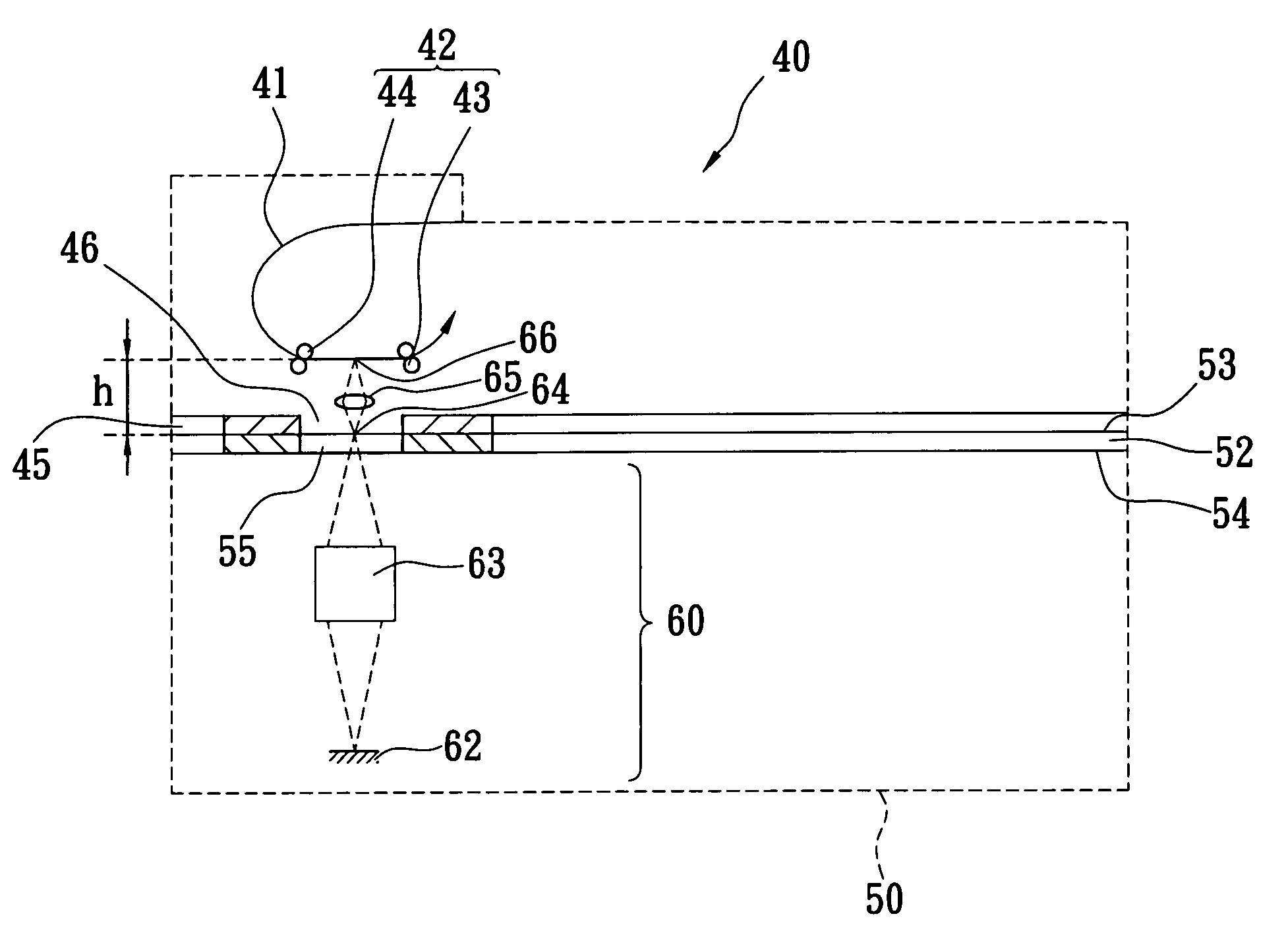
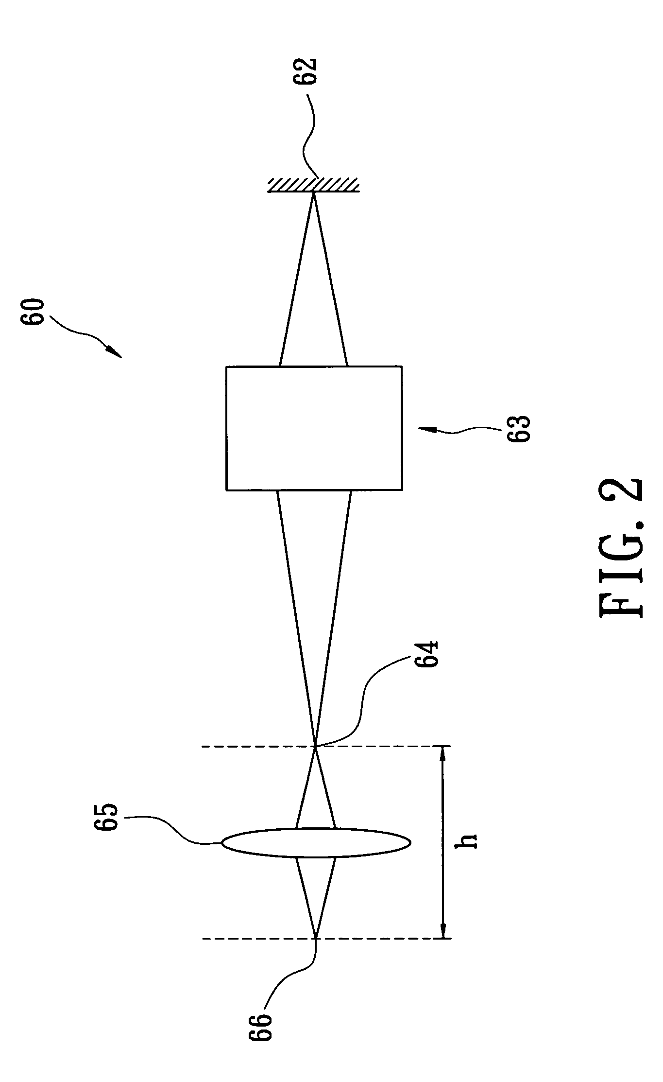
[0016]Referring to FIG. 2, an optical mechanism for increasing optical path in accordance with the present invention is shown, which comprises an optical-path device 60 and a light-focusing structure 65. The optical-path device 60 comprises an image sensor 62 and an optical module 63 for providing a scanning light. The light-focusing structure 65 is set in the optical path between the optical module 63 of the optical-path device 60 and the document to be scanned. The scanning light of the optical-path device 60 is focused and thus, forms a front focus 64. The light which passes through the front focus 64, and thus is dispersed, is focused on again and thus, forms a rear focus 66 through using the light-focusing structure 65. The rear focus 66 is the position for the document to be scanned. By means of the aforesaid arrangement, an optical path h between the front focus 64 and the rear focus 66 is added to the space that accommodates a document conveyer. In FIG. 2, a lens is used to ...


PUM


Abstract

An optical mechanism installed in an office machine, which has a machine base defining an internal space, and a paper-feeding mechanism arranged on the machine base, the paper-feeding mechanism having an inside receiving space and a bottom incident zone for the passing of light. The optical mechanism has an optical-path device formed of an image sensor and an optical module and mounted in the internal space inside the machine base, and a light-focusing structure mounted in the receiving space inside the paper-feeding mechanism above the incident zone for increasing optical path.

Description

[0001]This Nonprovisional application claims priority under 35 U.S.C. 119(a) on patent application Ser. No(s). 92215751 filed in Taiwan on Aug. 29, 2003, the entire contents of which are hereby incorporated by reference.BACKGROUND OF THE INVENTION[0002]1. Field of the Invention[0003]The present invention relates generally to an optical mechanism for use in an office machine, for example, a copy machine or scanner and, more particularly, to such an optical mechanism that increases the optical path of the office machine.[0004]2. Description of the Related Art[0005]A paper-feeding type office machine, for example, a copy machine or scanner, as shown in FIG. 1, generally comprises a paper-feeding mechanism 10 which comprises a sheet-transferring mechanism 12, which is adapted to transfer paper 11, and a machine base 20, which is disposed on the bottom side of the paper-feeding mechanism 10. The machine base 20 comprises a document carrier glass 22, which is disposed on the top side, an ...

Claims


Application Information

Patent Timeline
Patent Type & Authority Patents(United States)
IPC IPC(8): G03B27/52G03B27/62G03G15/04H04N1/04H04N1/031H04N1/10H04N1/12H04N1/193
CPCH04N1/031H04N1/12H04N1/1013H04N1/193H04N2201/02493
Inventor HUNG, MING TECHIANG, SHU-YUSU, YU-JENHSU, TIEN-HO
Owner LITE ON TECH CORP
Why Eureka
Try Eureka