Antenna Component

a technology of components and antennas, applied in loop antennas with ferromagnetic cores, polarised antenna unit combinations, instruments, etc., can solve the problems of large space and high cost of solution, and achieve the effects of small space, low cost and large amount of spa

Active Publication Date: 2018-03-22
EPCOS AG
View PDF5 Cites 1 Cited by
  • Summary
  • Abstract
  • Description
  • Claims
  • Application Information

AI Technical Summary

Benefits of technology

[0004]One possibility is to provide a separate antenna for each spatial direction in the receiver unit. However, this solution is costly and requires a large amount of space. In addition to the requirement for antennas of a small design and with low cost, in the last few years the requirements which are made of the physical properties of antennas for automotive applications have also increased continuously. The antennas are to be distinguished by a high level of sensitivity, that is to say, by high induced voltages for a given field and a large Q factor. Furthermore, they should be mechanically robust and may ensure a high level of reliability at low costs. For this purpose, in various embodiments, means of forming an electrical contact within the antenna structure may remain unaffected even under mechanical stress and short circuits between electrical conductors of the antenna may be avoided.

Problems solved by technology

However, this solution is costly and requires a large amount of space.

Method used


Image

  • Antenna Component
  • Antenna Component
  • Antenna Component

Examples


Embodiment Construction

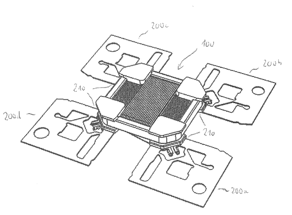
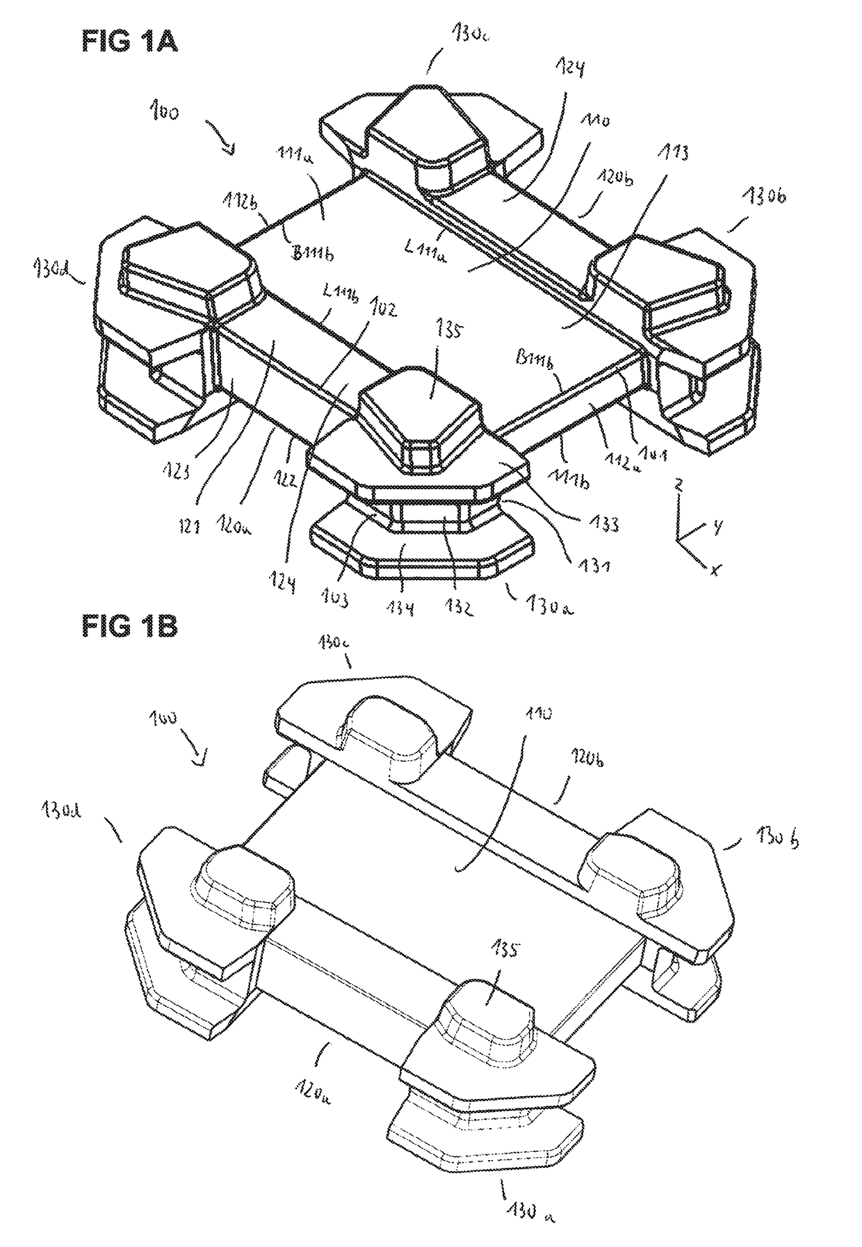
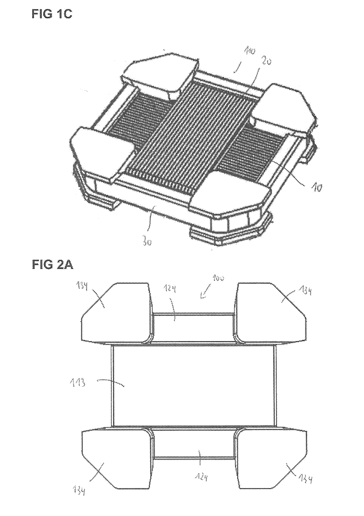
[0032]FIGS. 1A and 1B show a view of a first and second embodiment of a magnetic core 100 of an antenna component from an underside. In FIG. 1C, the magnetic core according to the configurations shown in FIGS. 1A and 1B is illustrated from an upper side. The magnetic core is wound with an electrical conductor 10, an electrical conductor 20 and an electrical conductor 30. The magnetic core 100 for winding with the electrical conductors 10, 20 and 30 is embodied as an integral or single-piece component. The electrical conductors are wound orthogonally with respect to one another, directly around the magnetic core 100.

[0033]The magnetic core 100 has a central cuboid section 110 with an upper rectangular side face 111a and a lower rectangular side face 111b, each with a relatively long side L111a and a relatively long side L111b lying opposite the latter, as well as a relatively short side B111a and a relatively short side B111b lying opposite the latter. As is illustrated in FIG. 1C, t...


PUM


Abstract

An antenna component is disclosed. In an embodiment the antenna component including a first, second and third electrical conductors and a magnetic core integrally embodied having different section, wherein the first, second and third electrical conductors are located at different sections of the magnetic core.

Description

[0001]This patent application is a national phase filing under section 371 of PCT / EP2016 / 056815, filed Mar. 29, 2016, which claims the priority of German patent application 10 2015 104 993.7, filed Mar. 31, 2015, each of which is incorporated herein by reference in its entirety.TECHNICAL FIELD[0002]The invention relates to an antenna component which can be used, in particular, in a receiver of a passive access authorization system and / or a passive authorization system for starting an engine, for example, of a vehicle.BACKGROUND[0003]In the last few years, various technologies have been developed for wireless access systems in automotive applications which permit passive access to the vehicle and passive starting of the vehicle. Such systems use low-frequency antenna systems which are provided in a transmitter unit in the vehicle and in a receiver unit of a radio key. An antenna which is integrated in the receiver unit must ensure the reception of signals in all three spatial directi...

Claims


Application Information

Patent Timeline
Patent Type & Authority Applications(United States)
IPC IPC(8): H01Q1/32H01Q7/06H01Q1/22G06K19/077
CPCH01Q1/3241H01Q7/06H01Q1/2225G06K19/07773H01Q21/24
Inventor JEREZ, FELIPEDRESPLING, ANNELIESEWALTER, ELMARBUEHLMAIER, STEPHANSCHLIEWE, JOERN
Owner EPCOS AG
Why Eureka
Try Eureka