Process of forming bend-controlling structures in a sheet of material, the resulting sheet and die sets therefor

a technology of bend control and sheet material, applied in the direction of shaping tools, handling devices, forging/pressing/hammering apparatus, etc., can solve the problems of unsatisfactory large number of punching or stamping die sets, product dimensions, etc., and the resulting sheet and die set are not suitable for slit dimensions. , the problem of slit lengths being complicated, and the inability to adjust the slit length to accommodate slits

Inactive Publication Date: 2007-05-29
IND ORIGAMI INC CA US
View PDF76 Cites 30 Cited by
  • Summary
  • Abstract
  • Description
  • Claims
  • Application Information

AI Technical Summary

Benefits of technology

[0023]The present process also includes a method for positioning bend-controlling structures relative to edges of the sheet of material and relative to weakened structural features, such as openings in the sheet of material. Such positioning can be achieved economically by using the stamping die sets for the end portions which define the bending straps first, and then, connecting the end portions with central portions.
[0028]Finally, substantial economic advantages also can be achieved by using a relatively small number of die sets formed to produce complete bend-controlling structures of varying length. A selection is then made from such die sets to produce a combination of bend-controlling structures of desired lengths, which are spaced along the bend line so that the number and width of the bending straps produces the desired bend strength, fatigue resistance and product performance characteristics.

Problems solved by technology

As will be appreciated, however, an approach which is based upon a different die set for each possible slit configuration and / or bending strap width can result in an undesirably large number of punching or stamping dies sets.
Product dimensions, for example, usually cannot be varied to accommodate slit dimensions, and particularly slit lengths.
Possible undesirable edge effects are further complicated by the desire to minimize scrap and by the fact that the slitting, grooving and displacing techniques taught in the prior related applications are particularly well suited for relatively complex folding of sheets.

Method used


Image

  • Process of forming bend-controlling structures in a sheet of material, the resulting sheet and die sets therefor
  • Process of forming bend-controlling structures in a sheet of material, the resulting sheet and die sets therefor
  • Process of forming bend-controlling structures in a sheet of material, the resulting sheet and die sets therefor

Examples


Embodiment Construction

[0071]Reference will now be made in detail to the preferred embodiment of the present invention, examples of which are illustrated in the accompanying drawings. While the invention will be described in connection with the preferred embodiments, it will be understood that the illustrated embodiments are not intended to limit the invention. On the contrary, the invention is intended to cover alternatives, modifications and equivalents, which may be included within the spirit and scope of the invention, as defined by the appended claims.

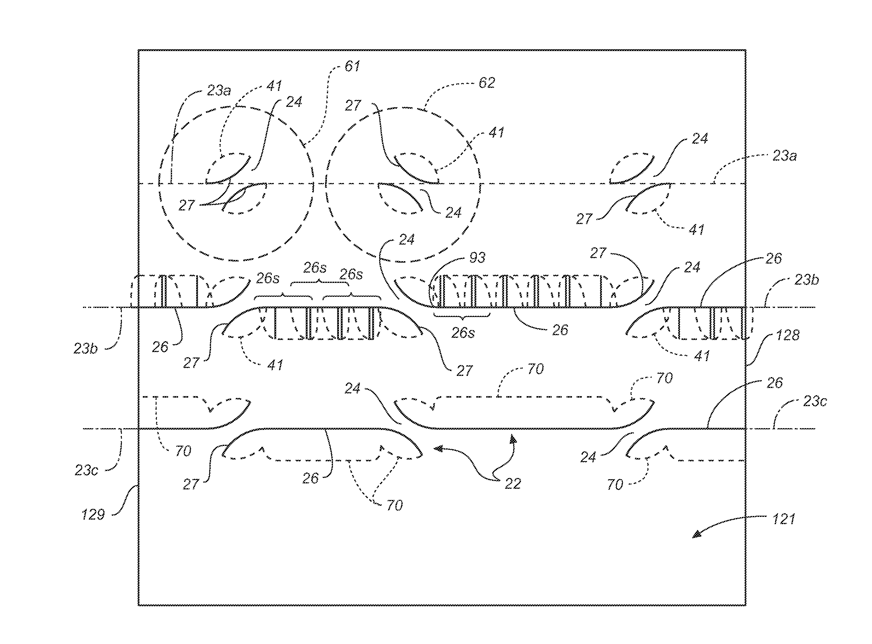
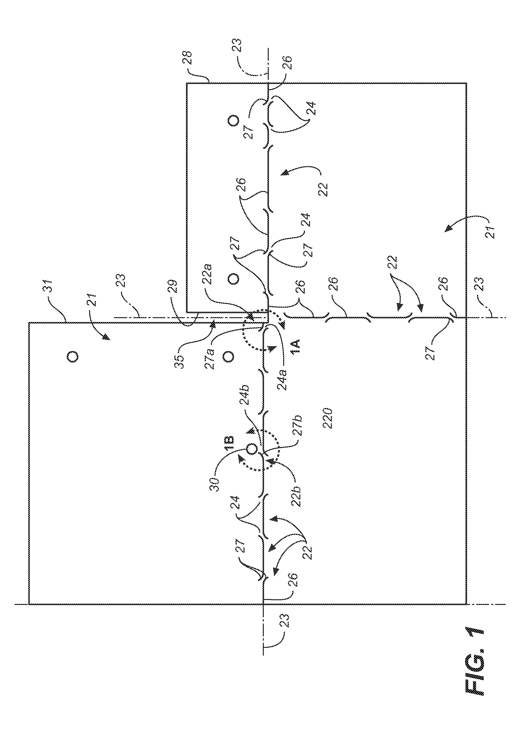
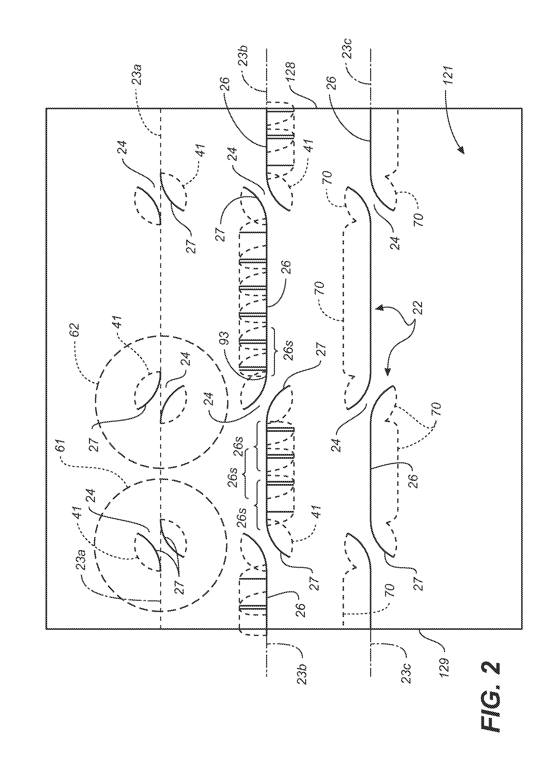
[0072]Referring now to FIG. 1, a sheet of material 21 is shown which has a plurality of bend-controlling structures, generally designated 22, formed therein along desired bend lines 23. In this case each bend-controlling structure 22 is shown as a slit which penetrates completely through the thickness dimension of sheet 21. As disclosed in the prior-related applications, grooves and displacements which do not penetrate completely through the thickness d...


PUM

PropertyMeasurementUnit
included angleaaaaaaaaaa

Abstract

A process of forming bend-controlling structures, such as slits, grooves or displacements (22), in a sheet of material (21, 121, 221, 321, 421, 521, 621, 721). The bend-controlling structures (22) have central portions (26) extending substantially parallel to a desired bend line (23) on the sheet and end portions (27) which diverge away from the bend line (23). In one embodiment the process includes the step of forming the bending straps (24) between pairs of slit end portions (27) at a desired spaced apart distances along the bend line (23) with the straps (24) having a desired configuration, and the step of forming central portions (26) which connect the end portions (27) to complete the slits (22) using a separate die set. A plurality of end portion dies (51 / 54) can be used to produce end portions (27) of various shapes and straps (24) of various widths, and a single set of central portion forming dies (71 / 74) are used to connect the end portions (27). In other embodiments die sets producing a single end portion (27) or mirror image impressions (A,B) are used and preferably overlapped to produce the complete bend-controlling structure (22). A modular die assembly (500) also is disclosed in which the bend-controlling structures can be produced by modular die inserts (511-514, 611-614). Finally, a selection of die sets (722a, 722b, 722c) of differing length from a group of die sets can be made to position the bending straps (24) at desired locations along the bend line.

Description

RELATED APPLICATIONS[0001]This application is a continuation-in-part application based upon a patent application Ser. No. 10 / 795,077, filed Mar. 3, 2004, now U.S. Pat. No. 7,152,450, and entitled Sheet Material with Bend Controlling Displacements and Method for Forming the Same, which is a continuation-in-part application based upon patent application Ser. No. 10 / 256,870, filed Sep. 26, 2002, now U.S. Pat. No. 6,877,349, and entitled Method for Precision Bending of Sheet Materials, Slit Sheet and Fabrication Process, which was a continuation-in-part application based upon a parent application Ser. No. 09 / 640,267, filed Aug. 17, 2000, and entitled Method for Precision Bending of a Sheet of Material and Slit Sheet Therefor, now U.S. Pat. No. 6,481,259 B1.TECHNICAL FIELD[0002]The present invention relates, in general, to methods of positioning and / or configuring bend-controlling structures, such as slits, grooves or displacements, in a sheet of material, and methods of using stamping o...

Claims


Application Information

Patent Timeline
Patent Type & Authority Patents(United States)
IPC IPC(8): B21D5/00B21D28/10
CPCB21D5/00B21D11/08B21D28/10B21D28/34B21D37/02B26F1/22B26D2007/0093Y10T83/0558Y10T83/8854B21D43/28B21D28/00
Inventor DURNEY, MAX W.ARNOLD, PHILIP M.
Owner IND ORIGAMI INC CA US
Why Eureka
Try Eureka