Energy absorbing device and shoulder belt-type vehicle seats comprising such energy absorbing device

a technology of energy absorption device and vehicle seat, which is applied in the direction of seat arrangement, support/holding device, aircraft crew accommodation, etc., can solve the problems of no solution regarding hic, no attention given to the new performance standards prescribed in c, and limitations

Inactive Publication Date: 2007-05-29
JTR ENG
View PDF13 Cites 18 Cited by
  • Summary
  • Abstract
  • Description
  • Claims
  • Application Information

AI Technical Summary

Benefits of technology

[0052]Resulting from this position of the backrest rotation axis, to make provision for passenger comfort in the lower back area, the support axle is preferably split in two parts on the left and right side of the backrest frame, thus avoiding to install an axle crossing the full width of the backrest. This configuration leads to concentrate the momentum of the backrest to one side of the frame engaged through the axle of the energy absorbing device, the other side being a free rotation axle with no momentum capacity. This design decision, resulting in one energy absorbing unit per backrest, has proved to be the most economical in weight and cost, as well as compatible with the curved shape of a pressurised aircraft cabin, forbidding installation of an energy absorbing device on outboard seats in most seating layouts.
[0065]This capacity to return to initial position and be available for a second or a third impact, is a distinctive advantage of the device according to the invention over the inflatable lap belt or any type of energy absorbing devices working on the seat structure.

Problems solved by technology

These known systems present serious drawbacks in view of the new standards for seats in transport category aircrafts issued in June 1998 by the U.S. Federal Aviation Administration (FAA) and the European Joint Aviation Authorities (JAA), to improve the chances of passenger survival in emergency landing.
It appears however that the new performance standards prescribed in § C didn't receive appropriate attention.
Most of the redesign effort was focused on the seat structure to comply with the § A and § B, leaving the protection of the occupants to a patchwork of partial measures for most of the requirements of § C, resulting in no solution regarding the HIC, with however the exception of an inflatable lap belt system, derived from the air-bag technology, associated to a conventional seat structure.
This process has however its limitations:Because the space available between seat rows is limited, to protect the egress path of the passengers in emergency conditions, the maximum stroke allowed to the seat structure by any type of energy absorption device is limited to 3 inches by the airworthiness authorities.While this stroke might provide some smoothing off the peak dynamic pulse, it has practically no effect on the occupant excursion.
Instead he will be allowed to pick-up speed relatively to the seat or the bulkhead in front, resulting in a secondary impact of the head which can be lethal.

Method used


Image

  • Energy absorbing device and shoulder belt-type vehicle seats comprising such energy absorbing device
  • Energy absorbing device and shoulder belt-type vehicle seats comprising such energy absorbing device
  • Energy absorbing device and shoulder belt-type vehicle seats comprising such energy absorbing device

Examples


Embodiment Construction

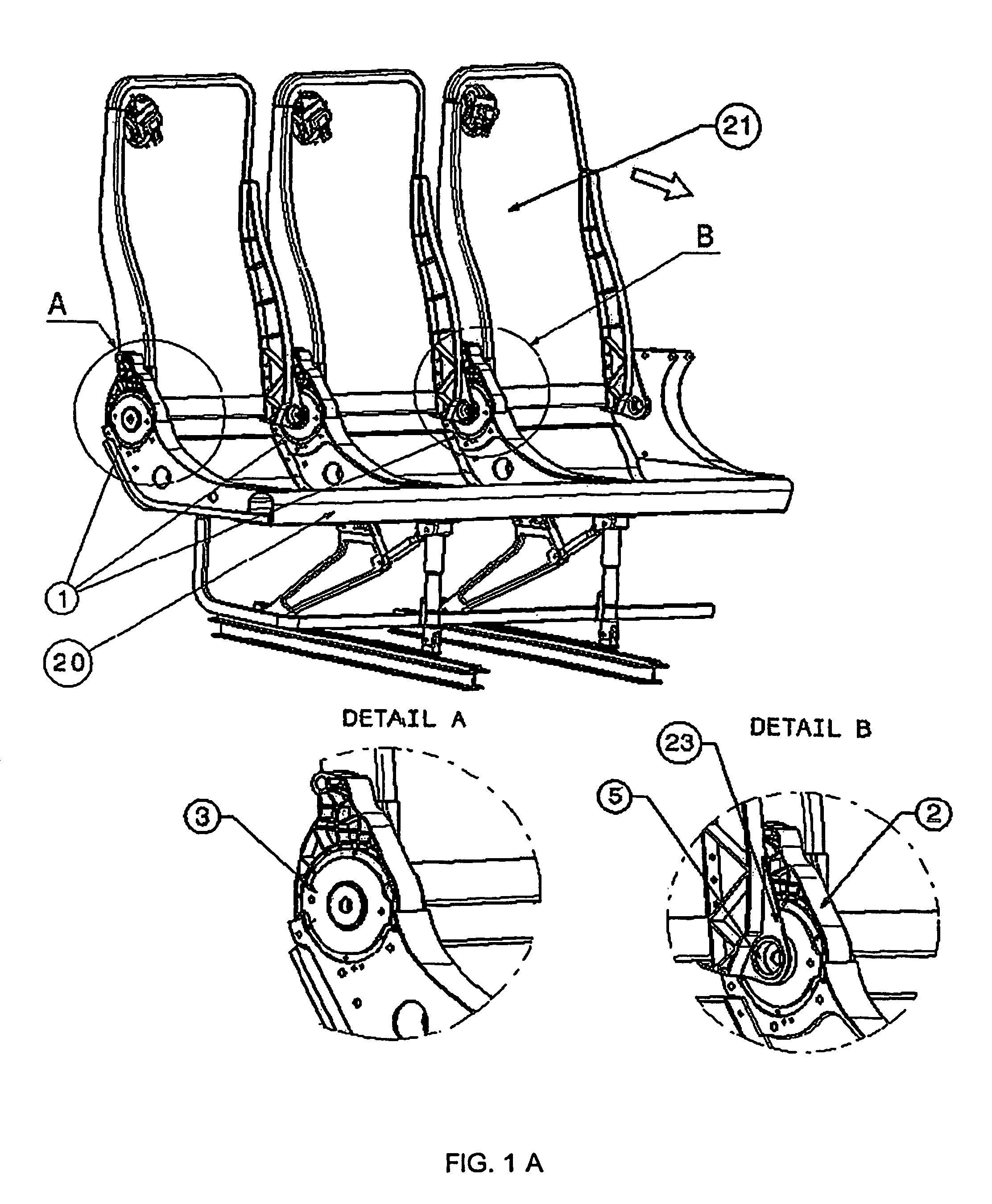
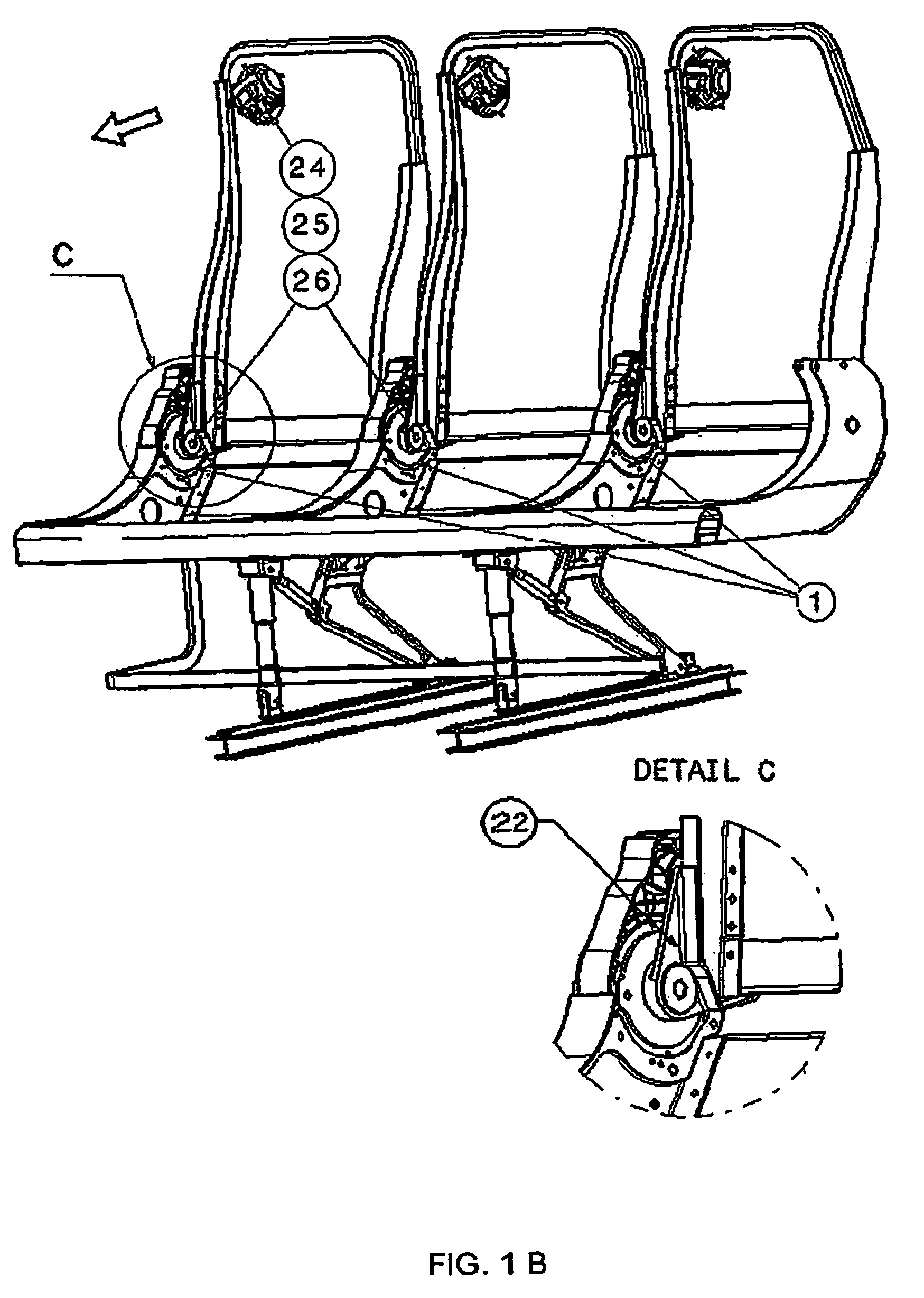
[0080]The following is a detailed description of a preferred embodiment of the invention, as illustrated in the attached drawings.

[0081]It will ompbe appreciated by anyone skilled in the art that many modifications and variations of the invention are possible in the light of the above teaching and within the boundaries of the appending claims, without departing from the general scope and spirit of the invention.

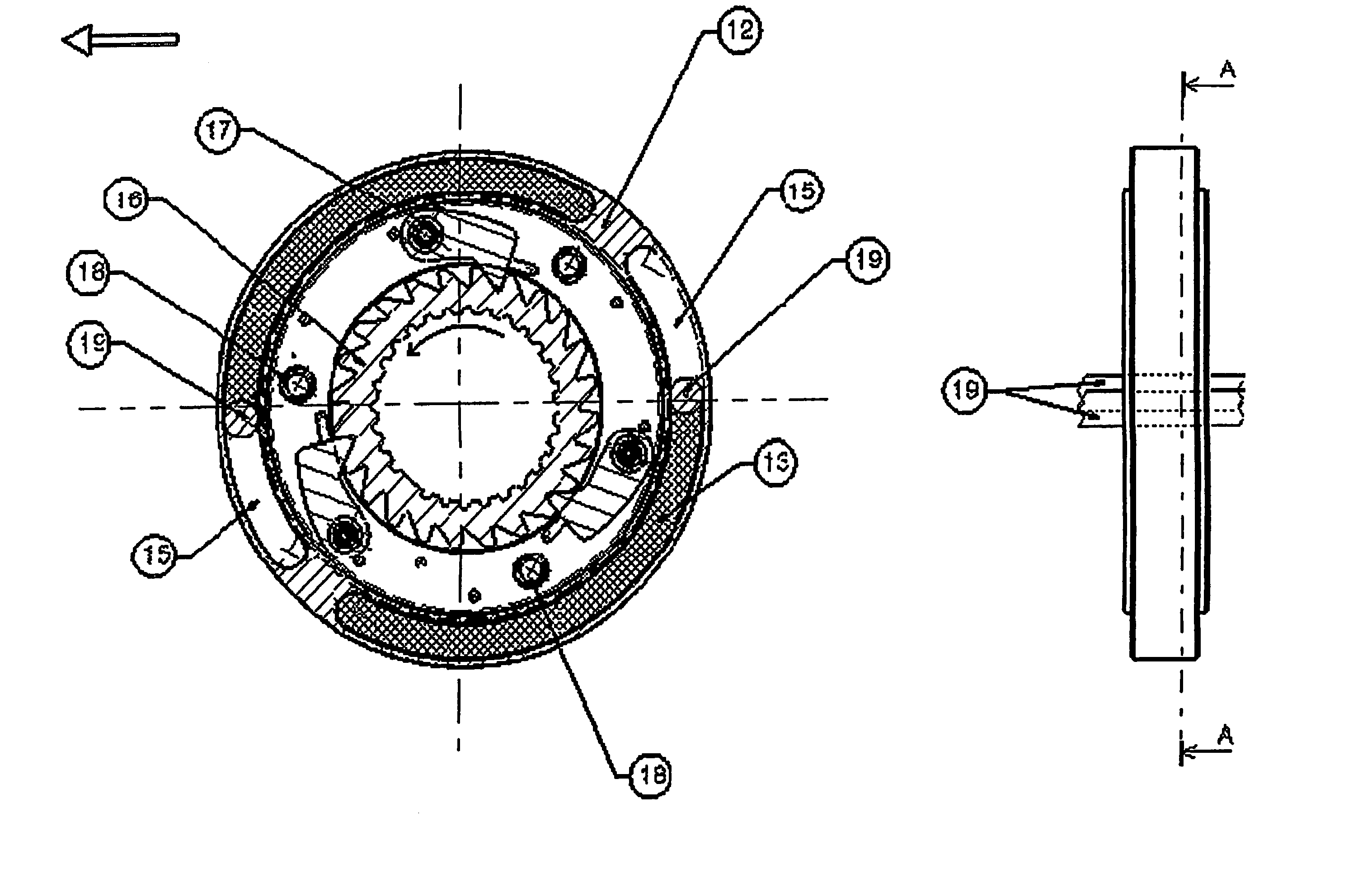
[0082]The energy absorbing device according to this embodiment of the invention, for use on an aircraft passenger seat, involves:

[0083]A casing (the support means referred to above), in the general shape of a flat cylinder containing the working parts of the energy absorbing function, including essentially a grooved shaft extending transversely in the adjacent backrest frame to engage in the internally grooved section of the adjacent backrest bracket, to form a rigid connection in torsion between the backrest frame and the energy absorbing device. Each casing is also rigidly ...


PUM


Abstract

The invention relates to a vehicle seat for equipment with shoulder belts (24) connected to the seat backrest (21), comprising an energy absorbing device (1) acting on the seat backrest, wherein said energy absorbing device comprises deformable energy absorbing means (12), with at least one arcuate (13, 14) area of plastically fragmentable material, opposing the rotation of said seat backrest (21) with respect to a lower seat structure (20) in a first direction, corresponding to a forward-leaning movement of said seat backrest. The invention also relates to energy absorbing devices opposing the rotation of a first part (1) with respect to a second part (2) via deformable energy absorbing means (12) with an arcuate area (13, 14) of plastically fragmentable material, wherein the energy absorbing device comprises releasable retention means (16) subjecting every rotation of said first part with respect to said second part into a first direction to the reaction of said energy absorbing means and allowing the rotation of said first part with respect to said second part, into the direction opposite to said first direction, without acting on said energy absorbing means.

Description

BACKGROUND OF THE INVENTION[0001]The invention relates to a mechanical device designed to dissipate kinetic energy, such as (part of) the kinetic energy of a vehicle seat (in particular an aircraft passenger seat) and its occupant, when involved in a survivable accident or incident (such as an emergency landing of an aircraft).[0002]More particularly the invention relates to such a device which can be used in connection with vehicle seats provided with shoulder belts.[0003]The expression “vehicle seat” as used in the present text refers to seats that are appropriate for road or other surface transport vehicles and for air transport vehicles; the vehicle seats to which the invention most suitably applies are seats for public transport vehicles and aircrafts.[0004]Several energy absorbing systems for transport category aircraft seats have been proposed in the art.[0005]Most of the know systems are however designed to absorb the energy in the underframe structure of the seat. Reference...

Claims


Application Information

Patent Timeline
Patent Type & Authority Patents(United States)
IPC IPC(8): B60N2/427B64D11/06B64D25/04F16F7/12
CPCB60N2/427B60N2/42745B64D11/06B64D25/04F16F7/12Y02T50/46B64D11/0649B64D11/0619B64D11/062Y02T50/40
Inventor DE WILDE, ROLANDBRAUN
Owner JTR ENG
Why Eureka
Try Eureka