Cable assembly with opposed inverse wire management configurations

a technology of management configuration and cable assembly, which is applied in the direction of cables, insulated conductors, coupling device connections, etc., can solve the problems of increasing manufacturing time and complexity, unable to readily align wires with the signal contacts of opposing circuit boards, and increasing the wire envelop

Active Publication Date: 2007-05-29
TYCO ELECTRONICS LOGISTICS AG (CH)
View PDF18 Cites 90 Cited by
  • Summary
  • Abstract
  • Description
  • Claims
  • Application Information

AI Technical Summary

Problems solved by technology

However, during assembly, the wires do not readily align with the signal contacts of the opposing circuit boards.
Rearranging the wires increases the manufacturing time and complexity and increases the envelope of the wires, thereby increasing the overall cost and size of the cable assembly.

Method used


Image

  • Cable assembly with opposed inverse wire management configurations
  • Cable assembly with opposed inverse wire management configurations
  • Cable assembly with opposed inverse wire management configurations

Examples


Embodiment Construction

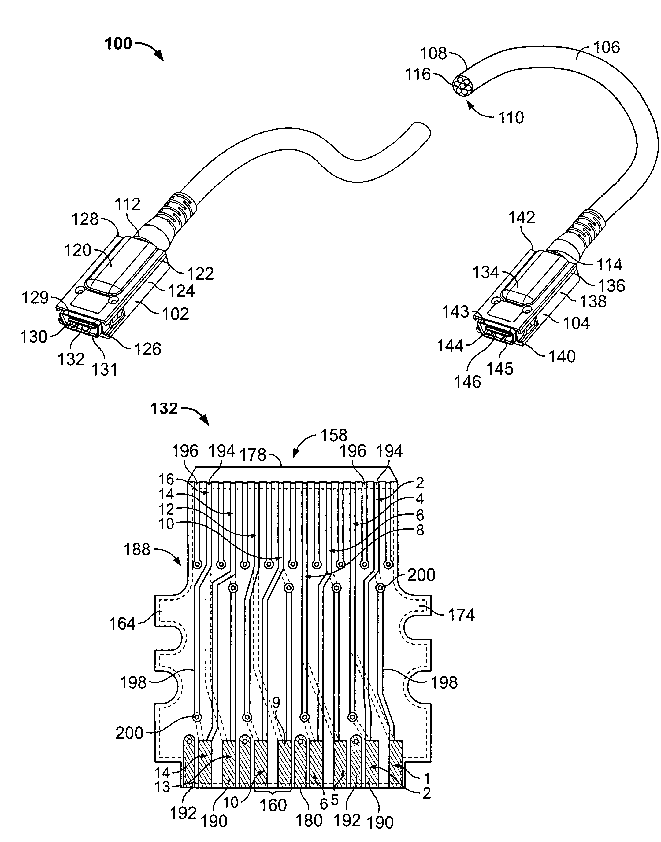
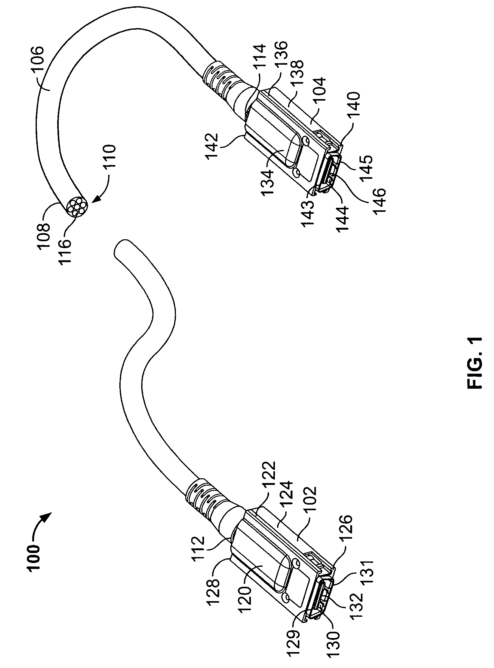
[0017]FIG. 1 illustrates a perspective view of a cable assembly 100 including a first electrical connector 102, a second electrical connector 104, and a cable 106 extending therebetween. The cable 106 includes an insulating cover 108 that circumscribes a wire bundle 110. The cable 106 has a first end 112 and a second end 114. The first end 112 is coupled to the first electrical connector 102, and the second end 114 is coupled to the second electrical connector 104. The wire bundle 110 includes a plurality of individually shielded wires 116 that may be arranged in differential pairs. Alternatively, the wire bundle may include un-shielded wires or groups of wires. Specifically, the wire bundle 110 includes sixteen wires 116 arranged in eight differential pairs having a helical shape. The wire bundle 110 has six differential pairs extending around the perimeter of the cable 106, and two differential pairs extending in the center of the cable 106. Alternatively, the wires 116 could be f...


PUM


Abstract

A cable assembly is provided that includes a wire bundle having individual wires, and first and second connectors provided on first and second ends of said wire bundle. The first and second connectors include first and second circuit boards, respectively. The first and second ends of the wires are terminated on the first and second circuit boards in accordance with different first and second wire management configurations, respectively.

Description

BACKGROUND OF THE INVENTION[0001]This invention relates generally to cable assemblies, and more particularly, to wire management configurations for cable assemblies.[0002]Modern electronic devices use cable assemblies to link various electronic components. Conventional cable assemblies typically include a cable having a wire bundle that extend between electrical connectors. In some applications, the electrical connectors include circuit boards that carry and are electrically coupled to various electronic components. The individual wires in the wire bundle are electrically and mechanically coupled at signal contacts on the circuit boards in the respective electrical connectors. The wires may be coupled to the circuit boards as differential pairs. As connectors and the circuit boards therein are reduced in size, less and less room is available for the wires to enter the connectors. Hence, it has become increasingly of interest to arrange the wires in a space efficient manner where the...

Claims


Application Information

Patent Timeline
Patent Type & Authority Patents(United States)
IPC IPC(8): H02G15/02H01R9/03
CPCH01R13/6658H05K1/0228H01R13/6471H01R13/6469H05K1/117H05K1/148H05K2201/10356H01R12/721
Inventor HACKMAN, JOHN A.
Owner TYCO ELECTRONICS LOGISTICS AG (CH)
Why Eureka
Try Eureka