[0020]Thus, only after the first one of the series-connected integrators has changed from its initial, high value into a value having an opposite sign, the second one of the integrators can start to react on this change, and only at the moment when the second one of the integrators has reached an output value having an opposite sign as compared to the initial output value of this integrator, the third one of the integrators can react on this change. Consequently, the time required for the control loop to get back into the linear region again, can be relatively long.
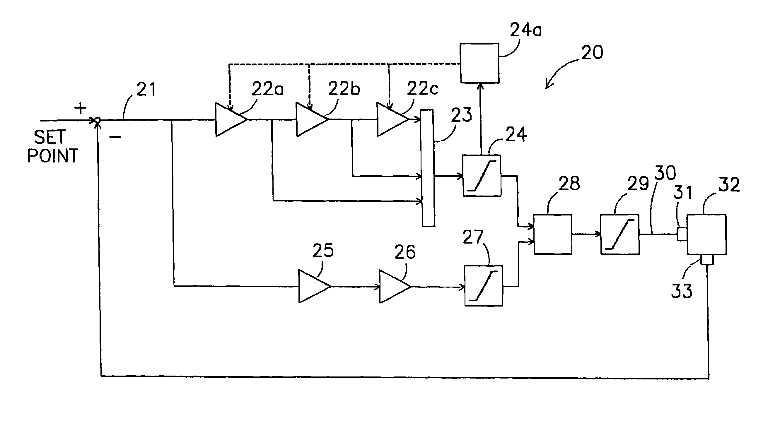
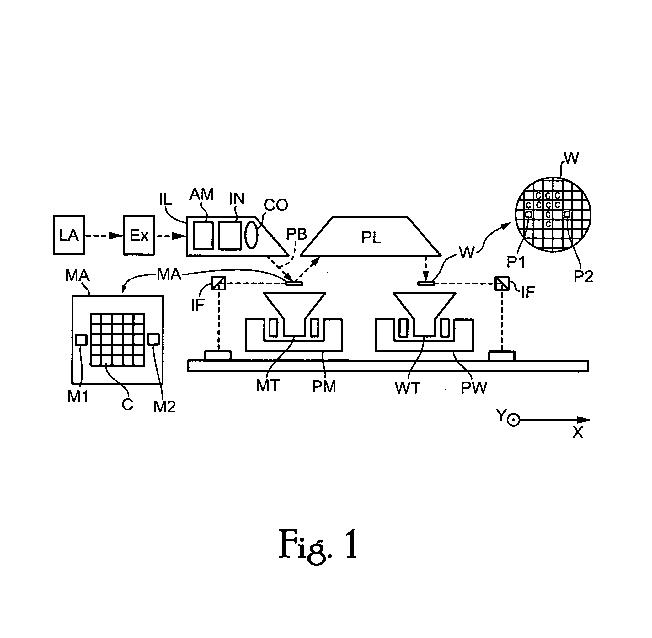
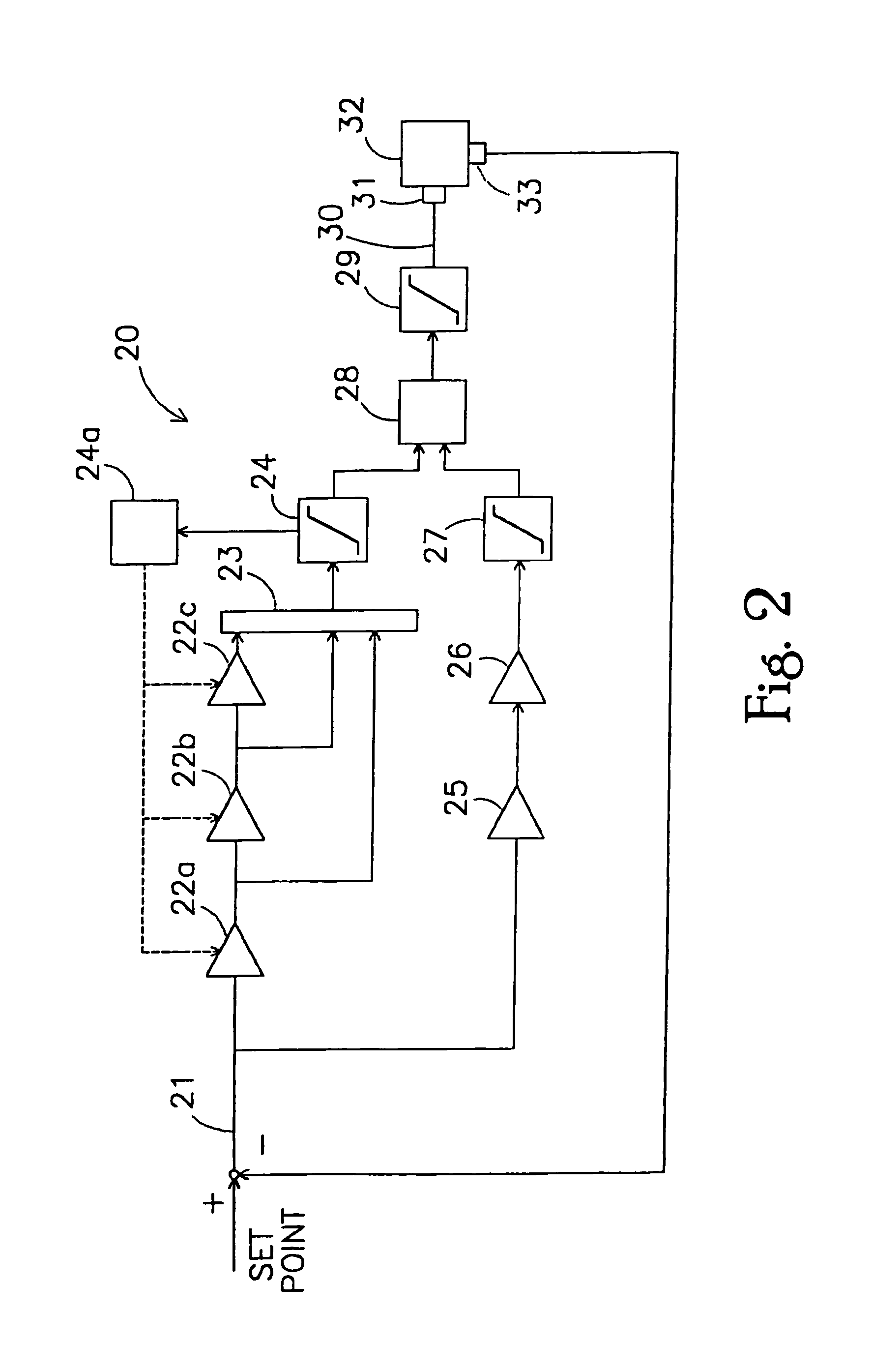
[0021]For at least these reasons, principles of the present invention, as embodied and broadly described herein, provide a lithographic apparatus which reduces the time for a control loop to reach the linear region. In one embodiment, the lithographic apparatus comprises a substrate holder configured to hold a substrate; a radiation system configured to condition a beam of radiation; a support structure configured to support a patterning device that imparts a desired pattern onto the beam of radiation, the support structure including a stage; a projection system that projects the patterned beam onto a target portion of the substrate; and a controller configured to control a quantity representing an attribute of a movable part of the apparatus. The controller comprises at least two integrators connected in series; an integrator output circuit configured to derive an output quantity of the series-connected integrators from a respective output quantity of at least one of the integrators of the series-connected integrators; an integrator saturator operatively coupled to the integrator output circuit, the integrator saturator having an operating region in which the output quantity is passes through and a saturation area in which the output quantity is limited; and a saturation control mechanism configured to set the output quantity of at least one of the series-connected integrators to a neutral value when the integrator saturator is in the saturation area, except when an input quantity or the output quantity of at least one of the series-connected integrators has a value that is capable of bringing the integrator saturator from the saturation region to the operating region.
[0027]The predetermined criterion can comprise at least one of a group comprising a startup of the control system, an instability of the control system, an overload condition, and an error condition. By bridging one or more of the integrators, the behavior of the controller can be altered in use, and with a suitable implementation (such as for example a numerical, digital implementation), it is possible to implement the bridging in such a way that at a moment of a change, such as an activation of a bridging or a deactivation of a bridging no changes at the output are observed, thus leading to a smooth transition (also referred to as bumpless transfer or bumpless parameter change), avoiding any steps, sparks or other transients which could lead to an error or temporary error in the value of the physical quantity.
[0028]Advantageously, at least one of the series-connected integrators comprises a series connection of an amplification stage and an integrator stage, an input of the integrator stage being connected to an output of the amplification stage, an amplification of the amplification stage being under control of a parameter change mechanism. Thus, when a parameter (such as the amplification) of the amplification stage is altered, sudden changes at the output of that integrator can be avoided, as only the output of the amplification stage and not the output of the integrator stage alters. Thus, sudden, such as stepwise, changes of the output quantity of the integrator are avoided, leading to a smooth, bumpless transition, i.e. it can thus be avoided that a change in a parameter leads to a sudden, undesired change in the value of the physical quantity.
[0030]Thus, advantageously, the integrators of the controller are comprised in a first branch, while other parts, such as a proportional or a differential (differentiator) transfer function are comprised in a second branch. The second branch is functionally parallel to the first branch, i.e. a same signal is applied to the inputs of both branches while the respective output signals of each of the branches are combined in a suitable manner, such as by means of addition. An advantage of the fact that the series-connected integrators are comprised in a separate branch of the controller is that it is now made possible to implement the saturator in the first branch, thus limiting the saturation action to the series-connected integrators. Alternatively, it is of course also possible that the saturator of the series-connected integrators is functionally located “after” the conjunction of the branches, i.e. thus saturating the combination of the output signals of the respective branches. The combination of the outputs of the branches can be in any suitable manner, however in an advantageous embodiment the output circuit comprises an adding unit for adding the respective output quantities in a weighted or un-weighted manner, leading to a practical implementation. In addition to, or instead of the controller saturator as described above, the controller can further comprise a second branch saturator for saturating an output quantity of the second branch and a controller output saturator for saturating an output quantity of the controller. In fact, in case of multiple branches, each branch can be provided with its own saturator for saturating an output quantity of the respective branch. In this manner, accuracy can be increased and a range of an output signal of the controller can be accurately limited, as each of the branches is equipped with its own respective saturator, while the output of the controller (i.e. comprising the respective output signals of each of the branches) also comprises a saturator. Also, in case of a change of parameters in operation (such as for example by bridging one or more of the integrators as described above, or any other change of any parameter in the controller), the occurrence of transients or steps or other sudden changes which could result in undesired sudden changes of the value of the physical quantity, can be largely eliminated.
[0033]The same or similar effects are achieved in another embodiment providing a method, comprising providing at least two integrators connected in series; deriving an output quantity of the series-connected integrators from a respective output quantity of at least one of the integrators of the series-connected integrators; passing through the output quantity when the output quantity does not exceed a predetermined value; limiting the output quantity when the output quantity exceeds the predetermined value; and controlling saturation by setting an output quantity of at least one of the series-connected integrators to a neutral value when the output quantity of the series connection of integrators exceeds the predetermined value, except when an input quantity or the output quantity of at least one of the series-connected integrators has a value that is capable of bringing the output quantity of the series-connected integrators below the predetermined value.

