

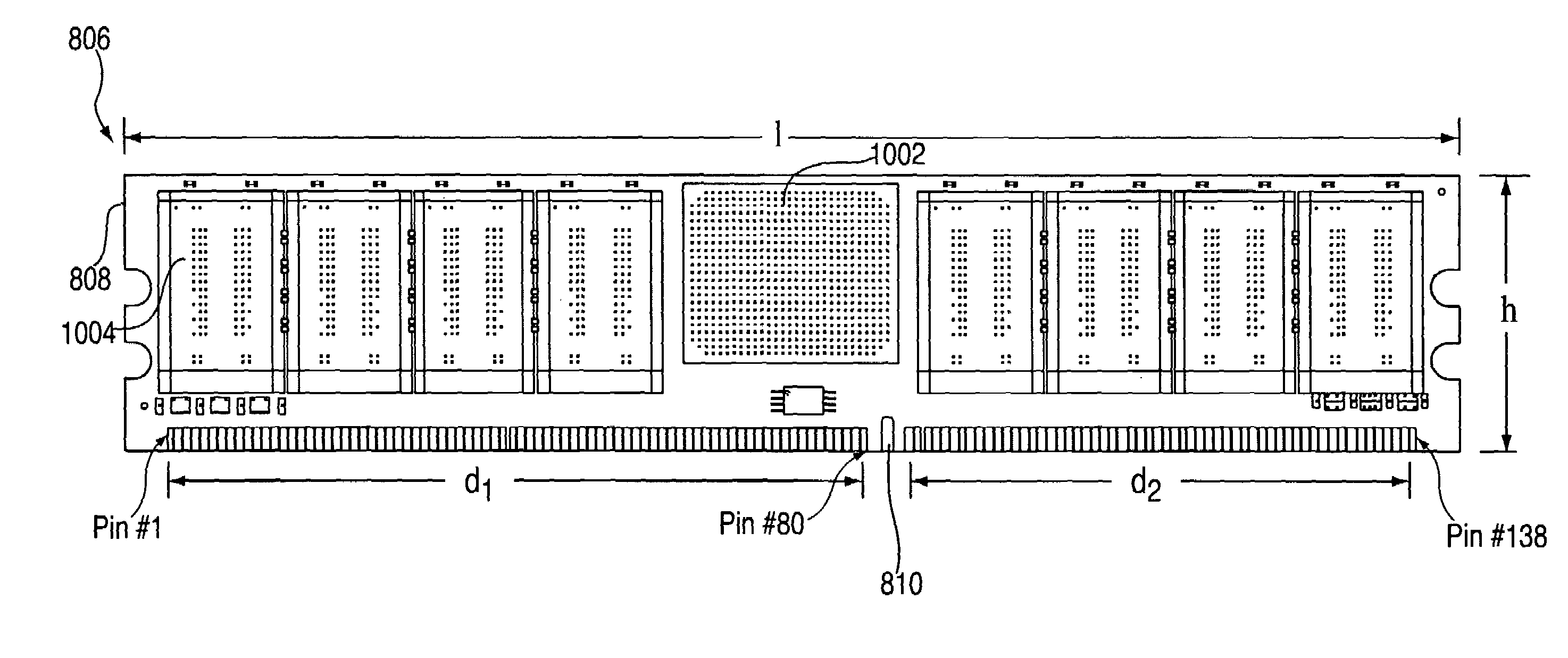
276-Pin buffered memory module with enhanced fault tolerance
a buffer memory module and fault tolerance technology, applied in the field of buffer memory modules with enhanced fault tolerance, can solve the problem of inherent limits on the number of modules that may be attached to the stub bus
- Summary
- Abstract
- Description
- Claims
- Application Information
AI Technical Summary
Problems solved by technology
Method used
Image

Examples
Embodiment Construction
[0031]Exemplary embodiments of the present invention include a flexible, high speed and high reliability memory system architecture and interconnect structure that includes a single-ended point-to-point interconnection between any two high speed communication interfaces. The memory subsystem may be implemented in one of several structures, depending on desired attributes such as reliability, performance, density, space, cost, component re-use and other elements. A bus-to-bus converter chip enables this flexibility through the inclusion of multiple, selectable memory interface modes. This maximizes the flexibility of the system designers in defining optimal solutions for each installation, while minimizing product development costs and maximizing economies of scale through the use of a common device. In addition, exemplary embodiments of the present invention provide a migration path that allows an installation to implement a mix of buffered memory modules and unbuffered and / or regis...
PUM
 Abstract
Description
Claims
Application Information