Power tool with an eccentrically driven working tool

a working tool and eccentric drive technology, applied in the field of power tools, can solve the problems of reducing the precision of the working tool guidance, affecting the service life of the working tool, and the wear of the guide roller, so as to reduce the additional mounting space, reduce the additional cost, and facilitate the replacement of the working tool.

Active Publication Date: 2007-06-05
HILTI AG
View PDF4 Cites 9 Cited by
  • Summary
  • Abstract
  • Description
  • Claims
  • Application Information

AI Technical Summary

Benefits of technology

[0011]By pivoting the first rollers of both or all roller pairs, in case that more than two roller pairs are provided, together, all of the roller pairs open simultaneously, providing for an easy removal or insertion of the working tool. Thereby, a rapid and easy replacement of the working tool is achieved.
[0018]It is advantageous when the pivot device is provided with a spring for preloading the at least one support member in the drive position, and an engagement cog is rotatably supported on the at least one support member for displacing the spring in its preloading position, with the cog being engageable by the radial cam. Thereby, there is provided a pivot device that insures a stable forcelocking connection between the rollers of the roller pairs and the working tool, while maintaining the manufacturing costs low.

Problems solved by technology

A drawback of the known power tool consists in that with the guide rollers being fixedly secured on the blade housing, wear of the guide rollers, which increases during their service life, cannot be compensated.
As a result, the precision of the working tool guidance becomes reduced with time, which reduces the operational life of the tool.
In addition, because of the fixed support of the guide rollers, the replacement of the working tool in the known power tool requires a relatively large amount of time and is very elaborate.

Method used


Image

  • Power tool with an eccentrically driven working tool
  • Power tool with an eccentrically driven working tool
  • Power tool with an eccentrically driven working tool

Examples


Embodiment Construction

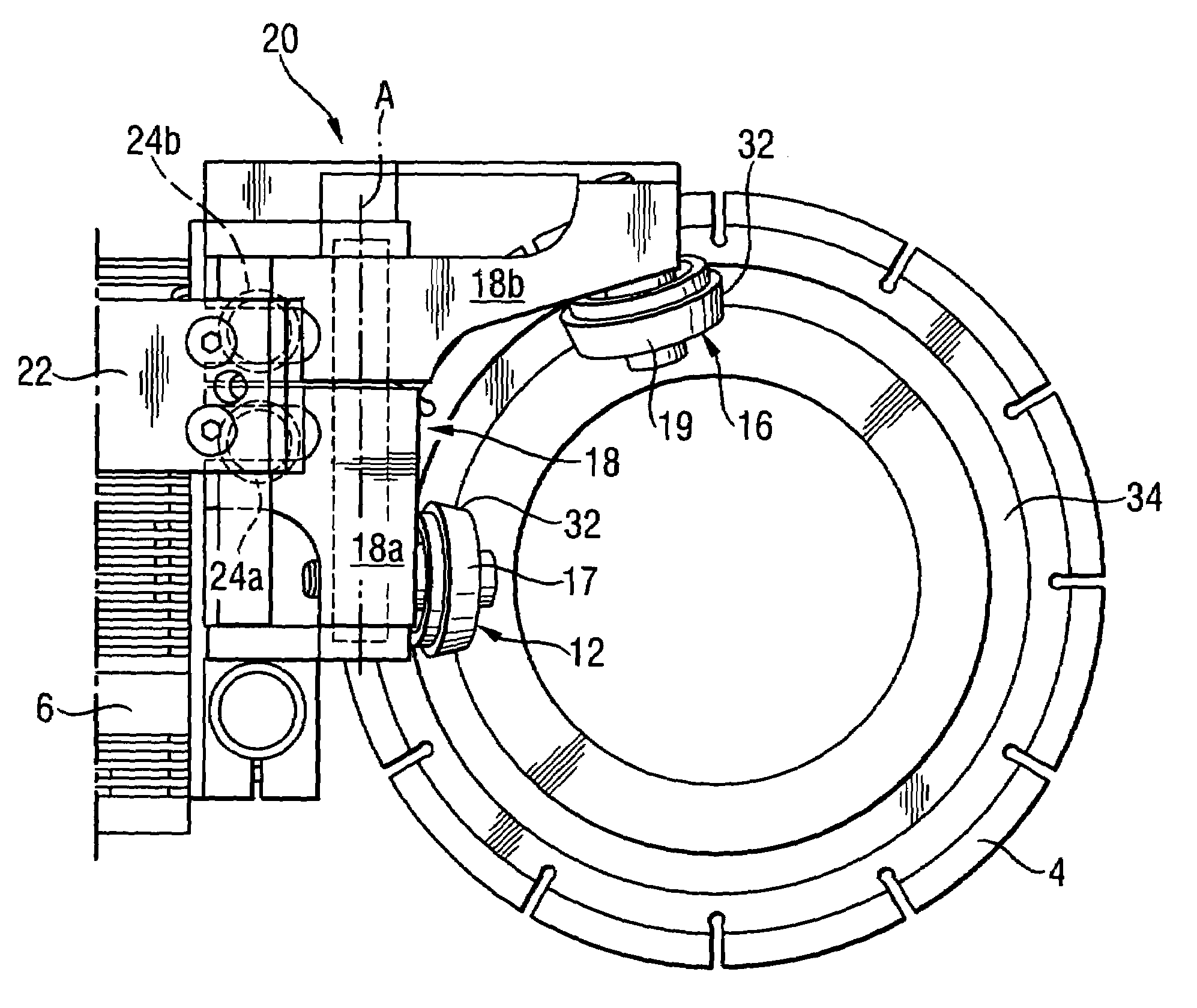
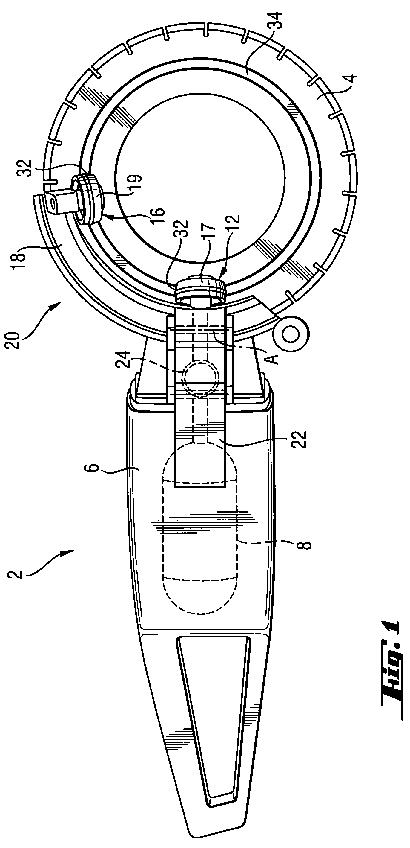
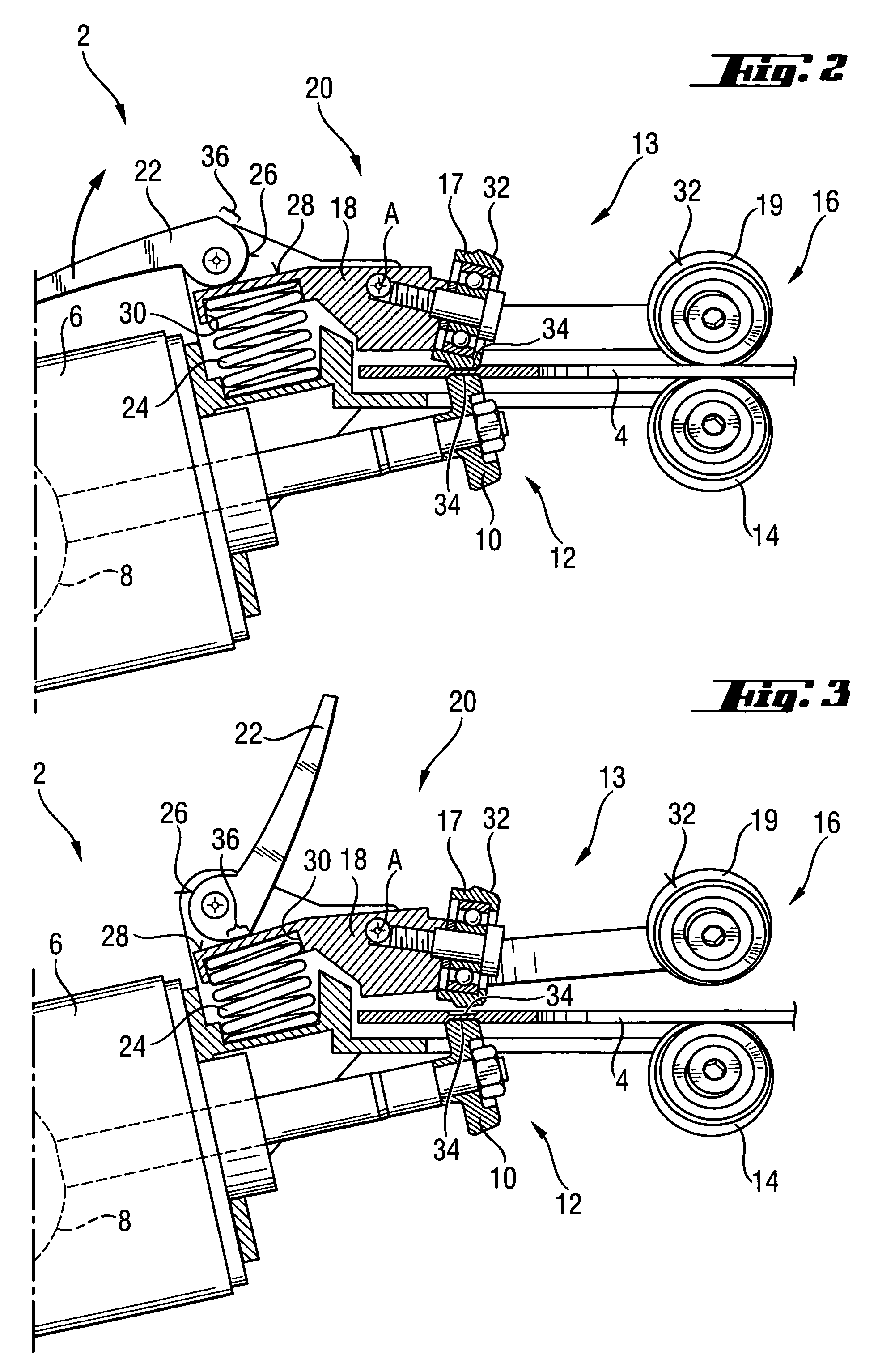
[0027]A power tool 2 according to the present invention, which is shown in FIG. 1, is formed as a circular saw with a circular working tool 4 in form of a disc that is eccentrically driven. The power tool 2 includes a housing 6, a motor 8 located in the housing 6 and rotatably connected with a first drive roller 10, which is formed as a friction wheel, of a drive roller pair 12 of a roller device designated generally with a reference numeral 13, as shown in FIG. 2.

[0028]As shown in FIGS. 2–3, the first drive roller 10 is supported on the housing 6 in a fixed spaced relationship to a first guide roller 14 of a guide roller pair 16. A second drive roller 17 of the drive roller pair 12, which is formed as a counter-pressure roller cooperating with the first drive roller 10, is rotatably supported, together with a second guide roller 19 of the guide roller pair 16, on a support member 18 of a pivot device 20. The support member 18 is supported on the housing 6 for a pivotal movement abo...


PUM

PropertyMeasurementUnit
axial forcesaaaaaaaaaa
radial displacementsaaaaaaaaaa
forcesaaaaaaaaaa

Abstract

A power tool, in particular a circular saw, for eccentrically a rotatable working tool and, in particular, a circular saw blade, includes a roller device (13) supported on a tool housing (6) and having at least two roller pairs (12, 16) each having a first roller (10, 14) and a second roller (17, 19) engageable with opposite sides of the working tool (4), with at least one of the rollers (10, 14, 17, 19) of at least one roller pair (12, 16) being rotatable by a tool motor (8) which is located in the housing (6), for driving the working tool (4), and a pivot device (20) for pivoting the first rollers (10, 14) together relative to the second rollers (17, 19) between a release position in which the working tool (4) is brought in or removed from the roller device (13), and a drive position in which a forcelocking connection between the at least one of the rollers (10) of the at least one roller pair (12, 16) and the working tool (4) is established.

Description

BACKGROUND OF THE INVENTION[0001]1. Field of the Invention[0002]The present invention relates to a power tool, in particular, a circular saw with an eccentrically driven working tool, in particular, a circular saw blade. The power tool includes a housing and a motor located in the housing. The power tool further includes a roller device supported on the housing and having at least two roller pairs spaced from each other and each having a first roller and a second roller. The first and second rollers of both roller pairs engage opposite sides of the working tool. At least one of the rollers of at least one roller pair is rotatable by the motor for driving the working tool.[0003]2. Description of the Prior Art[0004]In power tools of the type described above, as a rule, one roller pair is used for driving the working tool, with the working tool being clamped between one roller, which functions as a drive roller, and another, counter-pressure roller. The at least one another roller pair...

Claims


Application Information

Patent Timeline
Patent Type & Authority Patents(United States)
IPC IPC(8): B27B9/00
CPCB23D47/123Y10T83/9403
Inventor BLATZ, THOMAS
Owner HILTI AG
Why Eureka
Try Eureka