System for Ensuring Failsafe Operation of Pitot Tube Covers for Multiple Types of Pitot Tubes

Pending Publication Date: 2021-07-22
DEGROFF AVIATION TECH
View PDF1 Cites 1 Cited by
  • Summary
  • Abstract
  • Description
  • Claims
  • Application Information

AI Technical Summary

Benefits of technology

The present invention provides a pitot tube cover that automatically exposes the opening of the pitot tube when the vehicle reaches a predetermined speed. The cover is designed to be easily mounted on the pitot tube and removed automatically. The technical effects of this invention are automatic exposure of the pitot tube opening at high speeds, simplifying the design and lowering the cost of the cover, and ease of installation on the pitot tube.

Problems solved by technology

Unfortunately, insects, spiders or other vermin enter and / or build nests within the pitot tubes thereby interfering with an accurate reading of the ram air pressure and, thus, the air speed.
Conventional types of pitot tube covers are often costly and complicated.
When this happens, the pilot is without knowledge of the airspeed and is in a potentially dangerous situation.
Such contamination can occur while the aircraft is parked on a ramp or even in a hanger, causing obstruction and inaccurate airspeed indications.
There is a problem with conventional pitot tube covers, however.
Despite having large visible RBF (Remove Before Flight) Flags attached, numerous cases have been documented where pilots, or ground crew, fail to remove the pitot tube cover prior to taking off, thereby contributing to a potential catastrophe.
Prior art self-disengaging pitot tube covers are vulnerable to forces that cause them to rotate about the longitudinal axis of a round pitot tube.
This rotation could result in the pitot tube cover not automatically disengaging, and staying in place.
This is especially egregious in the case of aircraft at takeoff.
This can keep the cover from automatically self-disengaging, and can even make manual removal problematic.
Fouling of the pitot tube opening also can become an issue.
Exact fitting of a pitot tube cover for each type and size of pitot tube leads to substantial logistical challenges, and unnecessary expense.
A small number of each of the different pitot tube sizes and shapes requires only low volume production, resulting in relatively high production costs per piece.
When the material constituting the pitot tube cover is soft and fits closely around the pitot tube, there's a chance that the open end of the pitot tube will stick or bind due to the deformation of the softer surrounding material.
This could stop automatic disengagement from occurring, and could compromise the entire purpose of the pitot tube.
Because of the wide variety of vehicle types, sizes, and uses on which pitot tubes are mounted, installation of pitot tube covers is often problematic.
Very often, a maintenance crew cannot reach the pitot tube easily in order to install and / or remove the necessary pitot tube covers.
While a wide variety of different extension devices exist, none of them appear to be configured to easily interface with existing pitot tube covers.
This can render basic maintenance and protection of the pitot tube extremely difficult, and expensive.
Because some pitot tube cover materials are fragile, or do not admit to easy modification, additional structure to enhance pitot tube operation can be problematical.
Unfortunately, most of these are so invasive as to substantially degrade such materials as light weight cross-link polyethylene foam, which constitutes many conventional pitot tube covers.
Unfortunately, there is a tendency for some of the pieces to “hang up” on the pitot tube, especially when incomplete separation of the pitot tube cover pieces occurs.
Pieces of a pitot tube cover that continue to be “hung up” on the pitot tube can block the pitot tube, or create other hazards for aircraft in motion.
As designs for pitot tube covers become more elaborate (to address the many variations in operating conditions), the expense of the pitot tube covers also increases.
This can be anathema to earlier designs, which use flimsy materials, or entirely frangible materials.
Further, failsafe methods of reconnecting pitot tube cover parts into a whole cover so that safe, reliable self-disengagement will occur in the future add greater complexity and potential problems.
This in itself would increase the cost of the pitot tube cover structure.
However, low cost must also be maintained due to the difficulty of retrieving pitot tube covers after being released from moving aircraft.
Consequently, the conventional art does not meet the need for a safety pitot tube cover which will be automatically separated from the pitot tube once an aircraft, or other high speed vehicle reaches a predetermined speed.

Method used


Image

  • System for Ensuring Failsafe Operation of Pitot Tube Covers for Multiple Types of Pitot Tubes
  • System for Ensuring Failsafe Operation of Pitot Tube Covers for Multiple Types of Pitot Tubes
  • System for Ensuring Failsafe Operation of Pitot Tube Covers for Multiple Types of Pitot Tubes

Examples


Embodiment Construction

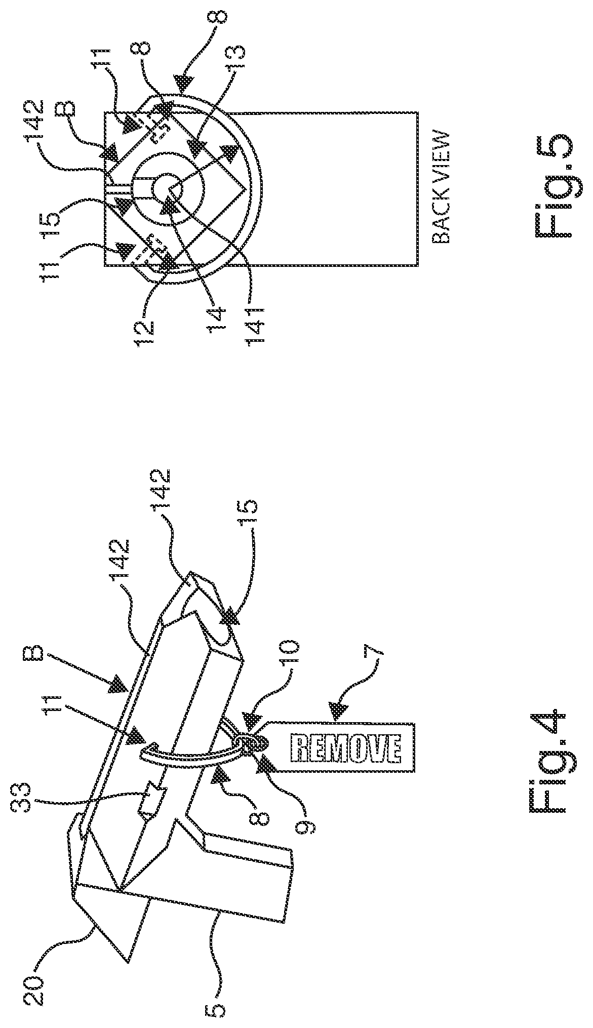
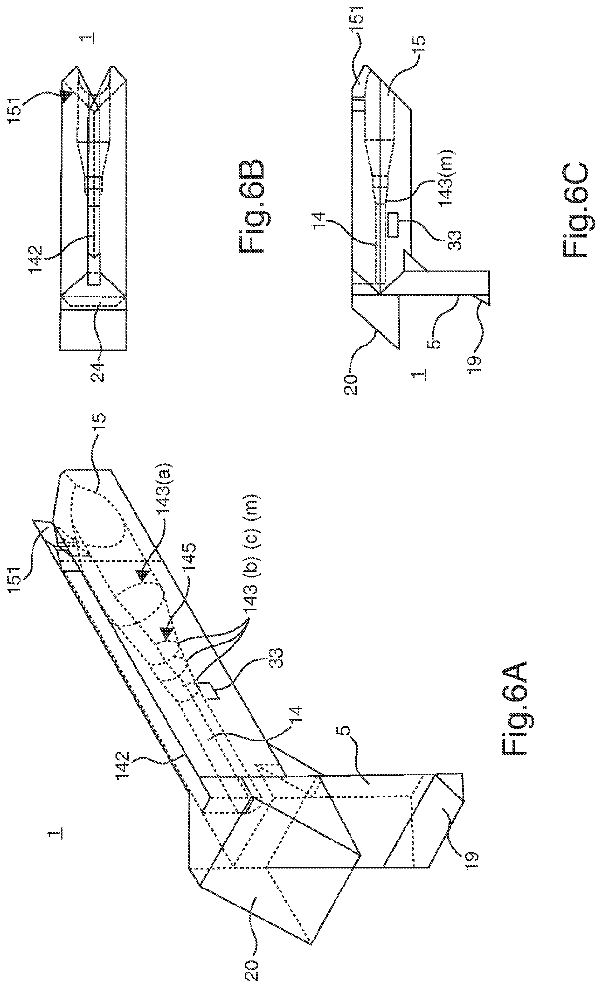
[0141]The first embodiment of the present invention operates in much the same manner as U.S. Pat. No. 5,938,147, to the same inventor as the present application. However, the pitot tube cover 1 of present invention has an airfoil configuration and a “keyhole” interior that substantially improve upon the operation of the cited conventional art. Further, many possible drawbacks that could be found in that prior art are avoided by one or more of the various aspects of the present invention. These various features operate cooperatively as a system which provides substantial reliability over that of the cited prior art.

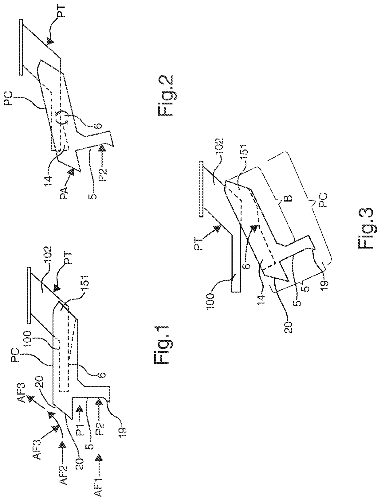
[0142]In order to guarantee a quick and trouble-free automatic disengagement of the pitot tube cover 1, a number of considerations are addressed by certain embodiments of the present invention. These include a more effective configuration to utilize air resistance as the motivating forces, AF1, AF2 and AF3 to remove the pitot tube cover 1, as depicted in FIGS. 1-3.

[0143]Mo...


PUM


Abstract

The present invention is directed to multiple arrangements of a self-disengaging pitot tube cover, which can be triggered by a plurality of different environmental conditions while the cover admits to a plurality of different latching mechanisms and opening configurations to guarantee the expeditious, automatic removal of the pitot tube cover while avoiding damage or contamination of the pitot tube itself.

Description

PRIORITY INFORMATION[0001]The present application claims priority from US Published Patent App. No: 2020 / 0331631; Ser. No. 16 / 851,348, filed Apr. 17, 2020, which claims priority from Provisional Patent App. No. 62 / 836,331, filed on Apr. 19, 2019; Provisional Patent App. No. 62 / 862,873, filed on Jun. 18, 2019; and, Provisional Patent App. No. 62 / 884,799, filed on Aug. 9, 2019.FIELD OF THE INVENTION[0002]The present invention is generally related to pitot tube covers for vehicles such as aircraft, and in particular the present invention is directed to a range of pitot tube covers, some of which are automatically removed by vehicle environmental conditions, and which accommodate automatic removal for a wide variety of different pitot tube conditions.BACKGROUND ART[0003]All aircraft (and occasionally other high speed vehicles), whether small general aviation aircraft or large airliners, have at least one pitot tube, or similar instrument input. Specifically, pitot tubes are the most com...

Claims


Application Information

Patent Timeline
IPC IPC(8): G01P1/02G01P5/165
CPCG01P1/026B64D43/02G01P5/165B64F1/005
Inventor DEGROFF, STEVEN A.RUSSEL, PHILLIP R.HOCKEMEYER, DAVID J.
Owner DEGROFF AVIATION TECH
Why Eureka
Try Eureka